
Rotational speed and torque control device and method of wind turbine generator set

A technology of wind power generating set, rotational speed and torque, which is applied in the control of wind power generator, wind power generator, wind power generation, etc. It can solve problems such as wind rotor rising, overspeed and overload, and lower quality of power generation, so as to reduce dynamic load and reduce power consumption. The effect of small speed fluctuation and improved stability

Active Publication Date: 2014-01-15
CSIC CHONGQING HAIZHUANG WINDPOWER EQUIP
View PDF5 Cites 0 Cited by
  • Summary
  • Abstract
  • Description
  • Claims
  • Application Information

AI Technical Summary

Problems solved by technology

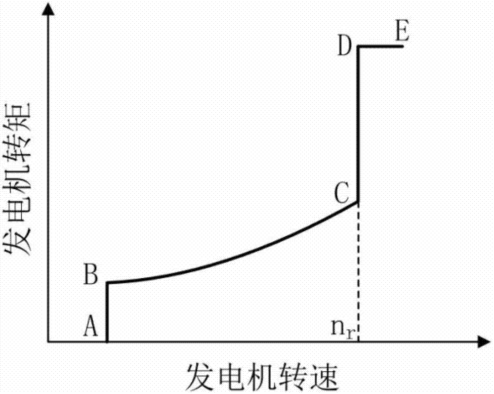
[0003] This method can make the wind turbine set in the optimal Cp control area to obtain the maximum wind energy in the area below the rated power, but it also has the following disadvantages: 1) The control transition between the CD section and the DE section is at the rated power point D, and there is no corresponding transition Because the natural wind conditions exist in turbulent state, when the wind speed fluctuates above and below the rated wind speed, the torque and pitch control will be switched frequently. Since the response speed of the pitch control lags behind the torque control, the two controls are not synchronized, resulting in the speed at no r Large fluctuations occur up and down, resulting in an impact on the unit; 2) The output power of the generator is the product of the speed and torque. Due to the influence of turbulent wind, the pitch control in the DE section cannot completely maintain the speed at the rated value. The use of constant torque control will cause the output power to change with the change of the generator speed, which will reduce the quality of the generated power; 3) The linear interpolation method used to calculate the parameter values ​​of the variable pitch PI controller in the DE section cannot effectively reflect the nonlinear aerodynamic characteristics of the fan blades. As a result, the followability of the pitch change action with the change of wind speed is reduced, resulting in large fluctuations in the speed of the DE section, and even adverse situations such as overspeed and overload.
[0004] Chinese Patent Publication No. CN101660489A discloses "a combined control strategy for megawatt-scale wind turbines". To alleviate the shortcomings of frequent switching between the two controllers in the above basic control scheme
However, the wind rotor of a megawatt fan has a relatively large inertia. When the fan works below the rated power point, the wind speed changes sharply, causing the wind rotor to accelerate and rise. Because the unit operates above the rated point, the pitch control is put into operation. Due to the influence of propeller response lag, this control method is likely to cause large fluctuations in speed and power, which will also cause impact on the unit

Method used


Image

  • Rotational speed and torque control device and method of wind turbine generator set
  • Rotational speed and torque control device and method of wind turbine generator set
  • Rotational speed and torque control device and method of wind turbine generator set

Examples


Embodiment 1

[0072] The wind conditions used in the simulation are: the average wind speed is 11.7m / s, and the turbulence intensity is 9.45%. The simulation results are as follows Figure 6-9 , the thick line in the figure represents the result of the control method of the present invention, and the thin line represents the result of other existing control methods. Figure 6 is the wind speed, Figure 7 is the rotor speed, Figure 8 is the pitch angle, Figure 9 for power. It can be seen from the result figure that when the wind speed fluctuates near the rated wind speed and the wind speed suddenly rises below the rated operating point using the control method of the present invention, the coordinated control of torque and pitch can better realize the flexible conversion of the control area, which is different from that of Compared with other existing control methods, the fluctuation of speed and power is greatly reduced, the stability of the unit under various wind conditions is improv...

Embodiment 2

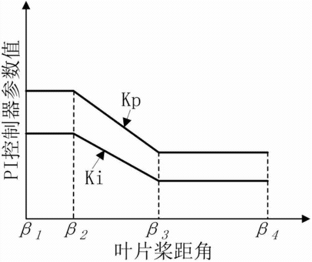
[0074] The wind conditions used in the simulation are: the average wind speed is 14m / s, and the turbulence intensity is 10.01%. The simulation results are as follows Figure 10-13 , the thick line in the figure represents the result of the control method of the present invention, and the thin line represents the result of other existing control methods. It can be seen from the result graph that the constant power control method of the present invention can effectively realize the stability of power output when the area above the rated wind speed is adopted. The non-linear pitch control parameter adjustment method realizes the nonlinear change trend control of the pitch action, enhances the followability of the pitch action with the change of wind speed, and ensures the stable operation of the fan speed. Compared with other existing control methods, it can significantly improve the stability of power output and speed, and can effectively reduce the limit and fatigue load of the...


PUM


Abstract

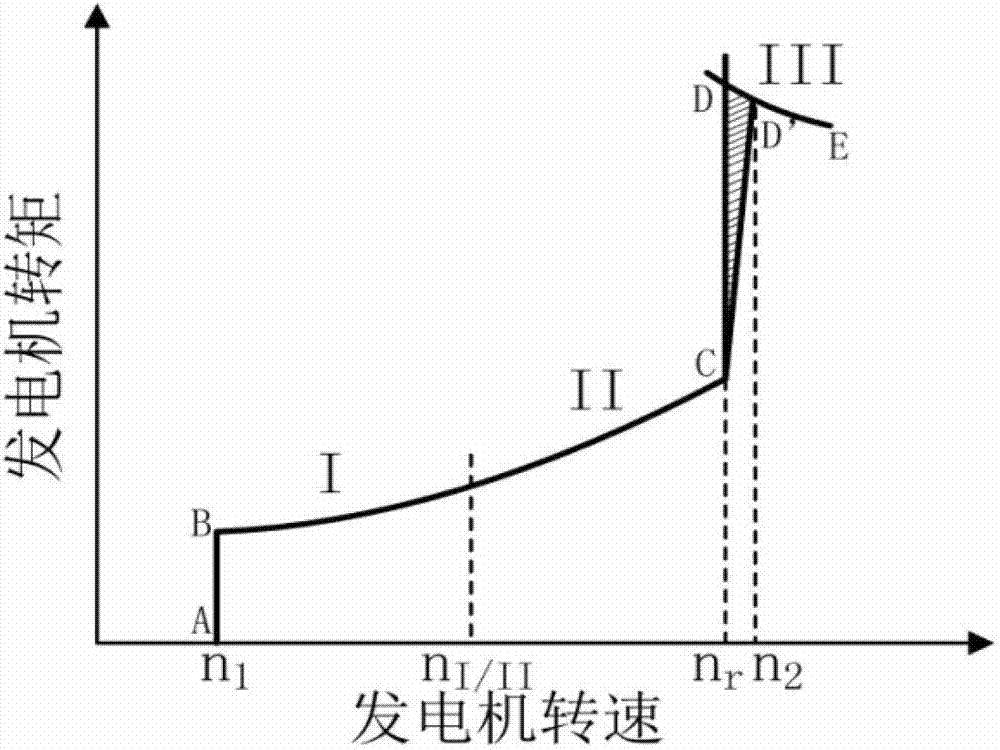
The invention discloses a rotational speed and torque control method of a wind turbine generator set. Under the situation that the measured rotational speed of a power generator is higher than the rated rotational speed and the measured power exceeds the rated power, the torque is switched from a PI (proportional-integral) control way to a constant power control way; under the situation that the pitch angle is smaller than the optimal pitch angle and the measured rotational speed is lowered below the rated rotational speed, the toque is converted from the constant power control way to the PI control way; and the pitch angle is controlled in a PI control parameter non-linear adjustment way, and the pitch control is in an activated state within the whole normal working rotational speed range. According to the rotational speed and torque control method of the wind turbine generator set provided by the invention, the problem of greater fluctuation in the rotational speed caused by desynchrony of the two types of control can be avoided by changing control target points of two controllers in a transition region, the transition region is improved from the original points to a curve, the flexible switching of the control states is easier to realize, and the stability in operation of the unit and the power output of the unit can be ensured.

Description

technical field [0001] The invention relates to the technical field of control of wind power generators, in particular to a device and method for controlling the speed and torque of wind power generators. Background technique [0002] The current control scheme of variable speed and variable pitch wind turbines is to use maximum power point tracking control to obtain the maximum wind energy at low wind speeds, and to use pitch control to limit wind energy absorption to keep power constant at high wind speeds. More specific implementations use figure 1 method shown. The three sections AB-BC-CD in the figure are the speed-torque relationship curves below the rated power of the generator, and point A corresponds to the minimum grid-connected speed n of the generator 1 , the DE section is the speed-torque relationship curve after reaching the rated power of the generator, and the point D corresponds to the rated power P r , the corresponding generator speed is the rated speed...

Claims


Application Information

Patent Timeline
Patent Type & Authority Patents(China)
IPC IPC(8): F03D7/00
CPCY02E10/723Y02E10/72
Inventor 杨微陶友传刘杰闫中杰刘亚林
Owner CSIC CHONGQING HAIZHUANG WINDPOWER EQUIP
Learn More