Laser three-differential cofocal theta imaging detection method

A differential confocal and imaging detection technology, applied in measuring devices, optical devices, instruments, etc., can solve the problem of limited measurement accuracy, light source intensity fluctuations, restrictions on confocal sensor focus tracking accuracy, poor confocal intensity response sensitivity, etc. problem, to achieve the effect of measuring range and resolving power

Inactive Publication Date: 2012-08-15
BEIJING INSTITUTE OF TECHNOLOGYGY
View PDF7 Cites 14 Cited by
  • Summary
  • Abstract
  • Description
  • Claims
  • Application Information

AI Technical Summary

Problems solved by technology

However, the existing confocal sensors have the following disadvantages: when the confocal intensity response hypotenuse is used for measurement, absolute displacement measurement cannot be achieved, and the measurement accuracy is limited by the nonlinearity of the confocal intensity response curve hypotenuse measurement interval and light source intens...

Method used


Image

  • Laser three-differential cofocal theta imaging detection method
  • Laser three-differential cofocal theta imaging detection method
  • Laser three-differential cofocal theta imaging detection method

Examples


Embodiment

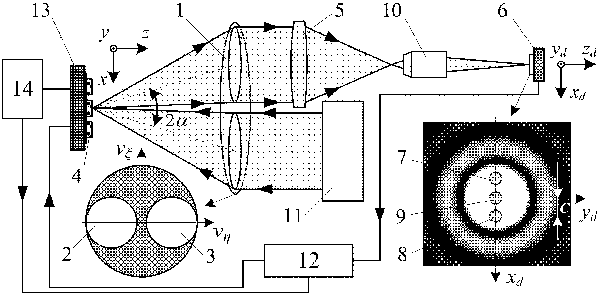
[0035] The embodiment structure of the present invention is as figure 2As shown, in order to facilitate the detection of the divided focal spot by the detector, in this embodiment, the image on the focal plane of the converging objective lens 5 is enlarged to the detection surface of the subsequent detector 6 through the magnifying objective lens 10 . The laser triple differential confocal theta imaging detection method of the present invention is further described as follows:

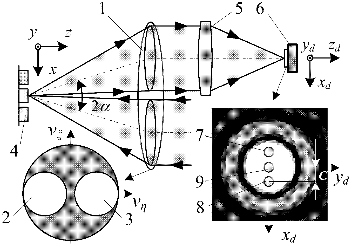
[0036] Such as figure 2 As shown, the parallel light beam emitted from the light source system 11 passes through the illumination pupil 2 and is converged by the objective lens 1 to the surface of the measured sample 4, and the reflected light carrying the information of the measured sample 4 passes through the collecting pupil 3 and is converged by the converging objective lens 5 On the detection surface of the detector 6, at the focal point in the detection surface, along the x d axis direction a...


PUM


Abstract

The invention belongs to the field of measuring a microfine structure of surfaces, relating to a laser three-differential cofocal theta imaging detection method. In the method, optical path arrangement with cofocal theta microscopy is adopted to scan and measure detected samples, the pupil plane of an objective lens is divided into a lighting pupil and a collecting pupil, an incident beam is converged on a detected surface by the objective lens after permeating the lighting pupil, reflected light carrying information of the detected samples is converged on a detection plane by a converging lens after passing the collecting pupil, three areas are arranged on a detected focal plane to obtain the response of the three areas and obtain the response characteristic equation of a detector, and the surface appearance and microscale of the detected samples can be reconstructed according to the intensity of a curve in a linear area or a position where the intensity is zero. In the method, the structure is simple, the resolution capability and range capacity can be effectively considered, and optical high-resolution absolute measurement on the surface appearance, three-dimensional microfine structure and the like of an object can be realized.

Description

technical field [0001] The invention belongs to the technical field of microscopic measurement, and in particular provides a method for high-resolution measurement that can be used to detect surface three-dimensional microstructures, microsteps, integrated circuit line widths and surface topography. Background technique [0002] In 1957, Marvin Minsky of the United States first proposed the concept of confocal microscopy technology. The original intention of this technology was to suppress the influence of stray light on the imaging quality by adding a detection pinhole in front of the detector, and to use a point light source to illuminate the sample. Carry out mobile scanning to realize the detection of information on different parts of the sample. Its lateral resolution is 1.4 times that of ordinary microscope systems with the same parameters, and it has unique optical tomography capabilities. However, due to the limitations of the "zero field of view" scanning imaging m...

Claims


Application Information

Patent Timeline
IPC IPC(8): G01B11/00G01B11/02G01B11/24G01B11/30
Inventor 赵维谦邱丽荣刘超
Owner BEIJING INSTITUTE OF TECHNOLOGYGY
Why Eureka
Try Eureka