Three-axis micro-mechanical gyroscope

A micro-machined gyroscope and gyroscope technology, applied in the field of micro-electromechanical systems, can solve the problems such as the inability to meet the requirements of miniaturization of gyroscopes, the development of three-axis gyroscopes, and the complexity of design and manufacture, and achieve good measurement accuracy and sensitivity. The effect of compact structure, reduced size and weight

Active Publication Date: 2012-08-15
BEIJING AEROSPACE TIMES OPTICAL ELECTRONICS TECH
View PDF2 Cites 18 Cited by
  • Summary
  • Abstract
  • Description
  • Claims
  • Application Information

AI Technical Summary

Problems solved by technology

[0003] The micromechanical gyroscope includes a driving part and a detecting part, and the measurement of the angular velocity of the motion is realized through the coupling of the driving and detection motions, so its design and production are complex, and it will be more difficult to realize a highly integrated three-axis gyroscope
At present, the design and production technology of single-axis gyroscopes has matured, while the development of three-axis gyroscopes is relatively lagging behind. Generally, multiple single-axis or two-axis gyroscopes are assembled orthogonally, or multiple gyroscopes are integrated on a single substrate. However, none of these can meet the miniaturization requirements of consumer electronics products. With the development of the market and the drive of emerging industries, the single-structure highly integrated micro-mechanical three-axis gyroscope will inevitably usher in an era of rapid development.

Method used


Image

  • Three-axis micro-mechanical gyroscope
  • Three-axis micro-mechanical gyroscope
  • Three-axis micro-mechanical gyroscope

Examples


Embodiment Construction

[0023] Below in conjunction with accompanying drawing and specific embodiment the present invention is described in further detail:

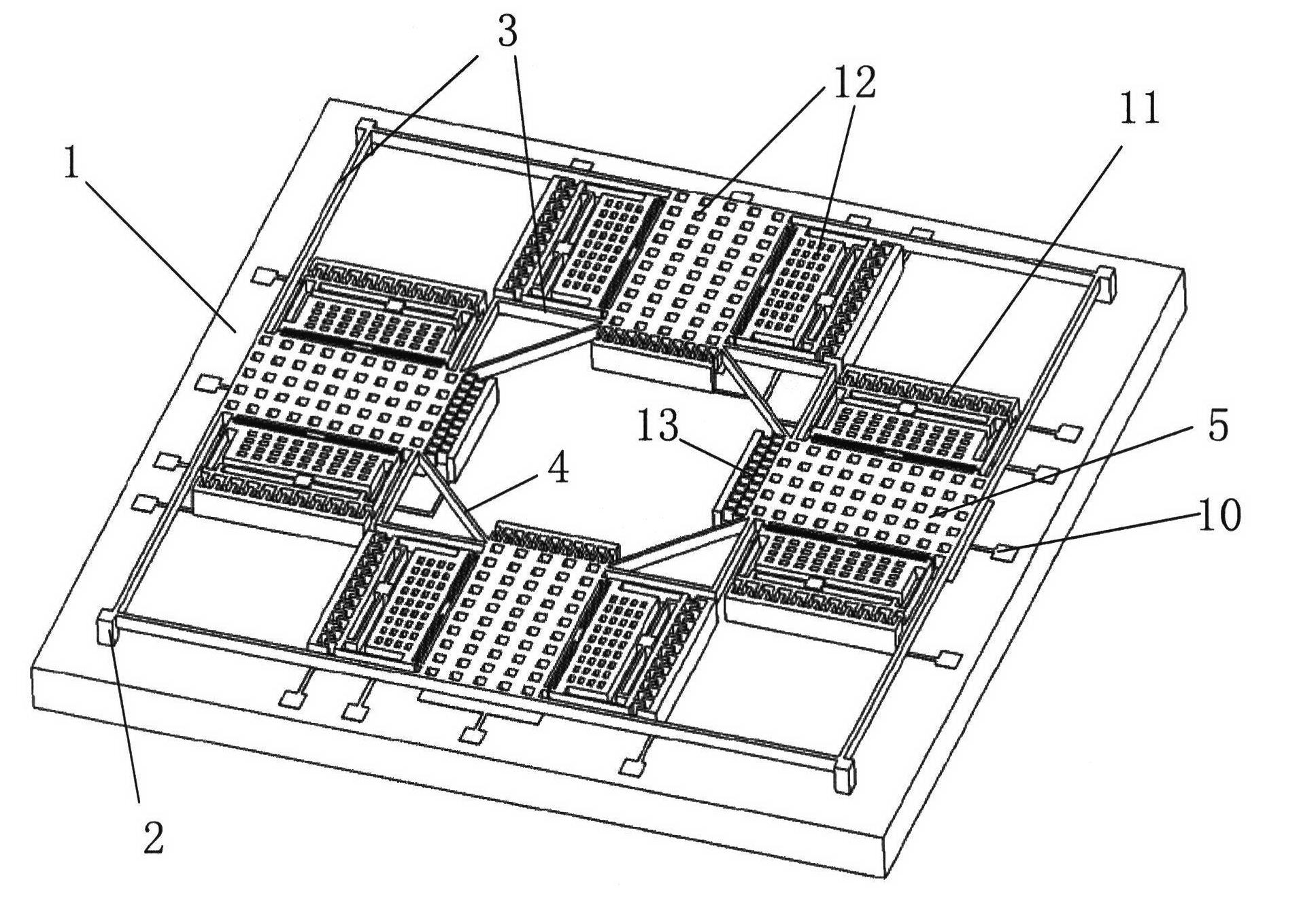
[0024] Such as figure 1 Shown is a three-dimensional structural schematic diagram of a single-structure micromechanical three-axis gyroscope of the present invention. The three-axis gyroscope includes a substrate 1 and a gyroscope structure 2 fixedly placed on the substrate 1. The gyroscope structure 2 is located at the center of the substrate 1. The gyroscope Instrument structure 2 is a through-hole structure in the middle, including plane detection units and z-axis detection units, which are distributed on the periphery of the structure layer and symmetrically distributed along the x-axis and y-axis directions.

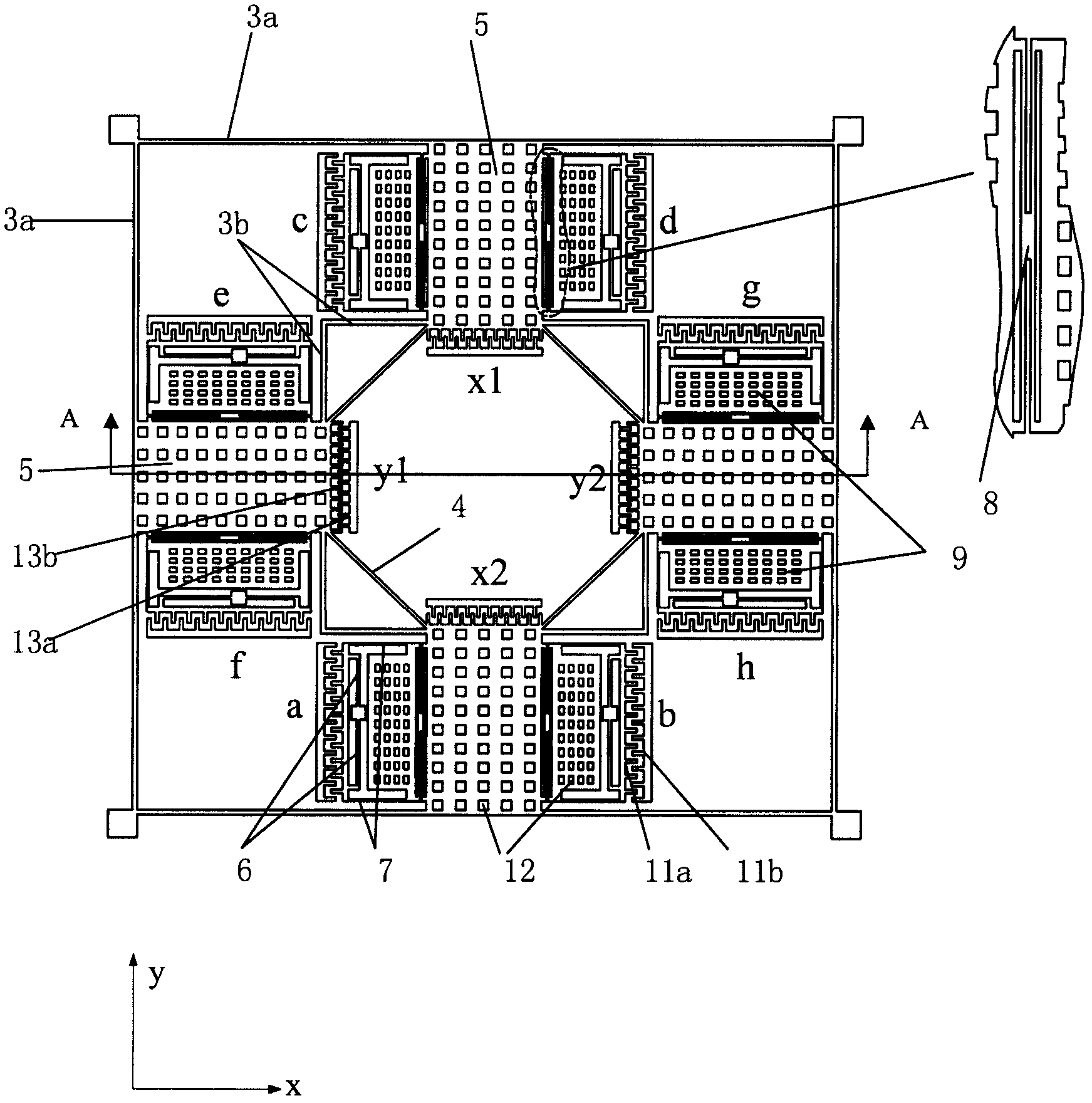
[0025] Such as figure 2 Shown is a schematic diagram of the structural layer of the single-structure micromachined three-axis gyroscope of the present invention. It can be seen from the figure that the plane detection unit includes ...


PUM


Abstract

The invention relates to a three-axis micro-mechanical gyroscope. The three-axis micro-mechanical gyroscope comprises a substrate and a gyroscope main body fixedly arranged on the substrate, wherein the gyroscope main body comprises a plane detecting unit and a z-axis detecting unit; the plane detecting unit comprises a first supporting beam, a linking beam, a driving electrode and a first mass block; the z-axis detecting unit comprises eight modules; and four modules are distributed at the two sides of a y-axis mass block along an x axis, the other four modules are distributed at the two sides of the x-axis mass block along a y axis, and each module comprises a second supporting beam, a decoupling beam, a driving beam, a second mass block and a detecting electrode. The three-axis micro-mechanical gyroscope has the advantages that the whole structure adopts a single-driving design and adopts a comb-tooth electrode for driving; the x axis and the y axis on the plane are detected by a variable-gap plate capacitor, the z axis is detected by a comb-tooth capacitor, and the x axis, the y axis and the z axis realize decoupling of driving and detection respectively; and the structure is compact, the manufacturing process is simple, the cost is low, the performance is higher, and good measuring accuracy and the sensitivity can be realized.

Description

technical field [0001] The invention relates to a micromechanical gyroscope, in particular to a single-structure three-axis micromechanical gyroscope with single drive and three-axis detection. It belongs to the field of microelectromechanical systems (MEMS). Background technique [0002] Micromechanical gyroscope is an inertial device based on micro-electromechanical system technology, which can be used to measure the angular velocity of object motion. Because it is designed and manufactured using MEMS technology, it has the characteristics of small size, light weight, suitable for mass production and low price, so It is applied in emerging industries such as consumer electronics products, such as digital camera image stabilization, motion control of game consoles, smart phones, handheld computers and micro-navigators. [0003] The micromechanical gyroscope includes a driving part and a detecting part, and the measurement of the angular velocity of the motion is realized t...

Claims


Application Information

Patent Timeline
Patent Type & Authority Applications(China)
IPC IPC(8): G01C19/56
Inventor 王巍张廷凯徐宇新邢朝洋庄海涵
Owner BEIJING AEROSPACE TIMES OPTICAL ELECTRONICS TECH
Why Eureka
Try Eureka