
Optical fiber vector vibration sensor

A sensor and optical fiber technology, applied in the field of orthogonal polarization optical fiber vector vibration sensor, can solve problems such as hidden dangers, safety, and susceptibility to electromagnetic interference, and achieve the effect of simple operation and good repeatability

Active Publication Date: 2012-08-15
JINAN UNIVERSITY
View PDF5 Cites 31 Cited by
  • Summary
  • Abstract
  • Description
  • Claims
  • Application Information

AI Technical Summary

Problems solved by technology

This type of electronic vibration sensor can be divided into moving coil type, eddy current type, piezoelectric type, piezoresistive type, etc. in terms of working principle, but the following problems generally exist: it is susceptible to electromagnetic interference, especially electronic devices are prone to sparks, and in There are safety hazards in the application in the field of oil and gas exploration
However, the miniaturized and networkable sensing technology based on a single optical fiber sensing unit to realize multi-dimensional vibration direction identification has not been reported yet.

Method used


Image

  • Optical fiber vector vibration sensor
  • Optical fiber vector vibration sensor
  • Optical fiber vector vibration sensor

Examples


Embodiment 1

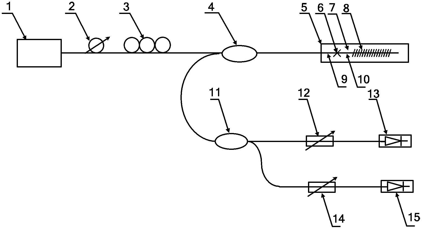
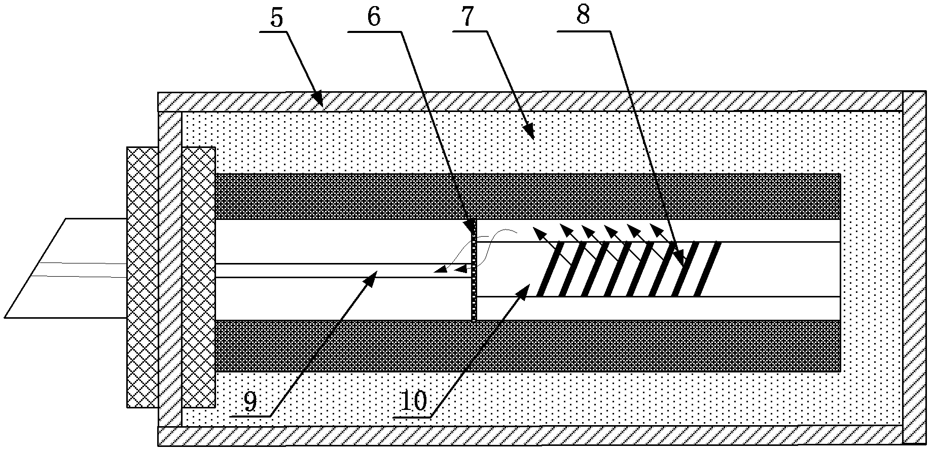
[0029] Such as figure 1 with 2 As shown, the fiber optic vector vibration sensor includes a broadband light source 1, a polarization control unit, a sensing probe, and an orthogonal polarization demodulation unit, and the polarization control unit, sensing probe, and orthogonal polarization demodulation unit pass through an optical fiber The circulator 4 is connected; the polarization control unit includes a polarizer 2 and a polarization controller 3, and the broadband light source 1, the polarizer 2 and the polarization controller 3 are connected in sequence; the sensing probe includes a support member, a housing, a polymer Elastic tube 5, optical fiber probe and optical fiber wire 16, described optical fiber probe comprises multimode tilted fiber grating 8 and cladding-core energy recoupling structure, the outer side of described polymer elastic tube 5 is protected by shell, polymer elastic tube 5 One end is fixed on the support member, the other end is suspended in the ai...

Embodiment 2

[0037] The structure of this embodiment is the same as that of Embodiment 1 except for the following features: the polarization control unit, the sensing probe and the orthogonal polarization demodulation unit are connected through a coupler.

[0038] The multimode tilted fiber grating 8 adopts a tilted grating with a tilt angle of 3 degrees.

[0039] The distance between the fusion point 6 where the multimode fiber segment 10 and the single mode fiber segment 9 are fused and the multimode tilted fiber grating 8 is 3 mm.

Embodiment 3

[0041] The structure of this embodiment is the same as that of Embodiment 1 except for the following features: the multimode tilted fiber grating 8 adopts a tilt angle grating with a tilt angle of 1 degree.

[0042] The distance between the fusion point 6 where the multimode fiber segment 10 and the single mode fiber segment 9 are fused and the multimode tilted fiber grating 8 is 4mm.


PUM

PropertyMeasurementUnit
Slopeaaaaaaaaaa
Diameteraaaaaaaaaa
Diameteraaaaaaaaaa

Abstract

The invention discloses an optical fiber vector vibration sensor. The optical fiber vector vibration sensor comprises a broadband light source, a polarization control unit, a sensing probe and an orthogonal polarization demodulation unit, wherein the polarization control unit comprises a polarizer and a polarization controller; the sensing probe comprises a multi-mode tilted optical fiber grating, a cladding layer-fiber core energy recoupling structure and a polymer elastic tube; the multi-mode tilted optical fiber grating and the cladding layer-fiber core energy recoupling structure are encapsulated in the polymer elastic tube and used for sensing environment vibration information; the multi-mode tilted optical fiber grating is made of a multi-mode optical fiber; the cladding layer-fiber core energy recoupling structure is welded in a manner of axially aligning multi-mode and single-mode optical cores; the orthogonal polarization demodulation unit comprises a polarization beam splitter, a filter and a photoelectric detector; and the polarization control unit, the sensing probe and the orthogonal polarization demodulation unit are connected by virtue of an optical fiber circulator or a coupler. The optical fiber vector vibration sensor disclosed by the invention can recognize two-dimensional vibration direction based on single optical fiber grating, and has the advantages of high sensitivity, compact structure, low cost and easiness for networking.

Description

technical field [0001] The invention relates to the field of vibration sensor design, in particular to an orthogonally polarized optical fiber vector vibration sensor capable of identifying vibration directions. Background technique [0002] Vibration sensors have a wide range of applications in the fields of building structural health detection, earthquake disaster prevention, oil and gas exploration, and national defense security monitoring. Timely diagnosis of its health status; by recording the source of the earthquake, studying the internal structure of the earth and the propagation characteristics of seismic waves, the impending earthquake prediction can be realized; by detecting the elastic waves caused by the reflection or refraction of the artificial vibration through the rock interface, the underground geological structure can be understood to find oil and gas traps to realize oil and gas storage exploration; by detecting ground waves caused by intrusion targets, t...

Claims


Application Information

Patent Timeline
IPC IPC(8): G01H9/00
Inventor 郭团关柏鸥
Owner JINAN UNIVERSITY
Learn More