
Indoor simulation experiment system for pipe-jacking grouting drag reduction

A simulation experiment and grouting system technology, applied in the field of construction engineering, can solve the problems of inability to simulate grouting to reduce drag, the pipe jacking grouting test has not been found, and the jacking process cannot be simulated, and the test results are accurate and reliable, and the structure is simple. , the effect of convenient operation

Inactive Publication Date: 2012-08-15
SHANGHAI JIAO TONG UNIV
View PDF4 Cites 37 Cited by
  • Summary
  • Abstract
  • Description
  • Claims
  • Application Information

AI Technical Summary

Problems solved by technology

This patented technology can be used to test the friction coefficient and friction resistance between the pipeline and the soil, but it cannot be used to test the friction coefficient and friction resistance between the pipeline and the soil in the pipe jacking project: 1. In the actual pipe jacking project, wrapped in the pipe The surrounding area is a mud sleeve instead of the original surrounding soil, so it is impossible to simulate the drag reduction of grouting; 2. In the actual pipe jacking project, the size of the pipe jacking head will be slightly larger than the size of the subsequent pipe joints, but the front and rear pipes are not exactly the same, so it cannot be simulated Actual jacking process
Further search did not find any reports on pipe jacking grouting test

Method used


Image

  • Indoor simulation experiment system for pipe-jacking grouting drag reduction
  • Indoor simulation experiment system for pipe-jacking grouting drag reduction
  • Indoor simulation experiment system for pipe-jacking grouting drag reduction

Examples


Embodiment Construction

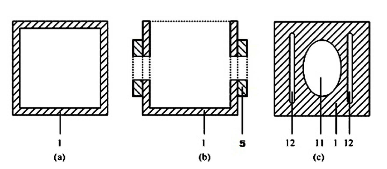
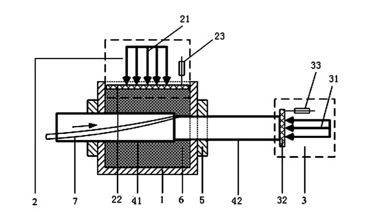
[0032] Such as figure 1 , figure 2 and Figure 4 As shown, the indoor simulation experiment system of pipe jacking grouting drag reduction in this embodiment includes a test box 1, the upper opening of the test box 1 is provided with a vertical loading test system 2, and the two opposite sides of the test box 1 are provided with An oblong hole 11, and a horizontal loading test system 3 is provided on one side thereof. A soil sample 6 is buried in the test box, and the pipeline 4 to be tested passes through the test box through the oblong holes 11 on both sides of the test box.

[0033] The indoor simulation experiment system of pipe jacking grouting drag reduction of the present embodiment also includes a grouting system 9 and a grouting conduit 7 connected with the grouting system, and the pipeline 4 to be tested is composed of a pipeline front section 41 and a pipeline rear Section 42 constitutes, and the pipe diameter of pipeline front section 41 is slightly thicker tha...


PUM


Abstract

The invention discloses an indoor simulation experiment system for pipe-jacking grouting drag reduction, which comprises an experiment box. An opening and a vertical loading test system are arranged on the experiment box; obround holes are arranged on two opposite sides of the experiment box; a horizontal loading test system is arranged on the one side of the experiment box; the experiment box is internally filled with a soil sample; a pipe to be tested penetrates through the experiment box via the obround holes on the two sides of the experiment box. The experiment system also comprises a grouting system and a grouting pipe connected with the grounding system; the pipe to be tested is formed by a front pipe segment and a rear pipe segment that are connected with each other; and the diameter of the front pipe segment is larger than that of the rear pipe segment; at least one grouting hole is configured on the wall of the pipe to be tested; and a slurry outlet end of the grouting pipe extends in the pipe to be tested and is connected with the grouting holes. According to the invention, the experiment test can simulate pipe-jacking process in soil layers; mixed slurry is injected to surrounding soil during the jacking process to test frictional resistance and frictional coefficient during the pipe-jacking process under different slurry proportions and different grouting pressures, so that the grouting pressure and the grouting proportion suitable for pipe-jacking in the soil layers can be obtained comprehensively and accurately.

Description

technical field [0001] The invention relates to a test device in the technical field of construction engineering, in particular to an indoor simulation experiment system for pipe jacking grouting and drag reduction. Background technique [0002] The pipe jacking technology is to use the hydraulic cylinder to jack the pipe jacking machine and the pipe joints to be laid underground one by one from the pipe jacking working well without excavating the surface until the trenchless underground pipeline laying in the pipe jacking receiving well. construction process. It has the following advantages: high construction precision, wide application of soil quality, wide range of applicable pipe diameters, low construction cost, and small impact on the surrounding environment. With the acceleration of urbanization in our country, pipe jacking technology is widely used in the construction of underground pipe networks such as urban water supply and drainage, gas, electric power, and comm...

Claims


Application Information

Patent Timeline
IPC IPC(8): G01N19/02
Inventor 陈楠陈锦剑王建华夏小和吴琼
Owner SHANGHAI JIAO TONG UNIV
Learn More