
Front end buck convertor lossless buffer circuit for controlling superpower high-speed motor

A snubber circuit and high-power technology, which is applied in the field of motor control and non-destructive snubber circuit, can solve the problems of long reverse recovery time, large switching loss, high switching frequency, etc., and achieve the effect of reducing the total volume, reducing loss, and facilitating capacity expansion

Inactive Publication Date: 2012-08-15
NANJING UNIV OF AERONAUTICS & ASTRONAUTICS
View PDF4 Cites 13 Cited by
  • Summary
  • Abstract
  • Description
  • Claims
  • Application Information

AI Technical Summary

Problems solved by technology

However, high-speed motors work at high speeds, and the corresponding switching tubes have high operating frequencies and large losses.
In the freewheeling stage under high-frequency modulation mode, the current is realized through the body diode or integrated diode of the power switch tube, and the loss is large. The usual power tube body diode has the disadvantage of long reverse recovery time.
Some scholars have proposed to connect a Buck circuit composed of a high-frequency power chopper tube and a freewheeling diode after the DC input terminal, and then connect it to the winding through a three-phase bridge inverter circuit. However, in high-speed and high-power applications, the Buck circuit is due to The switching frequency is high and the switching loss is large, which reduces the life of the power switch tube and the efficiency of the entire circuit, and the power level is difficult to increase due to the limitation of the voltage and current capacity of the switch tube itself.

Method used


Image

  • Front end buck convertor lossless buffer circuit for controlling superpower high-speed motor
  • Front end buck convertor lossless buffer circuit for controlling superpower high-speed motor
  • Front end buck convertor lossless buffer circuit for controlling superpower high-speed motor

Examples


Embodiment Construction

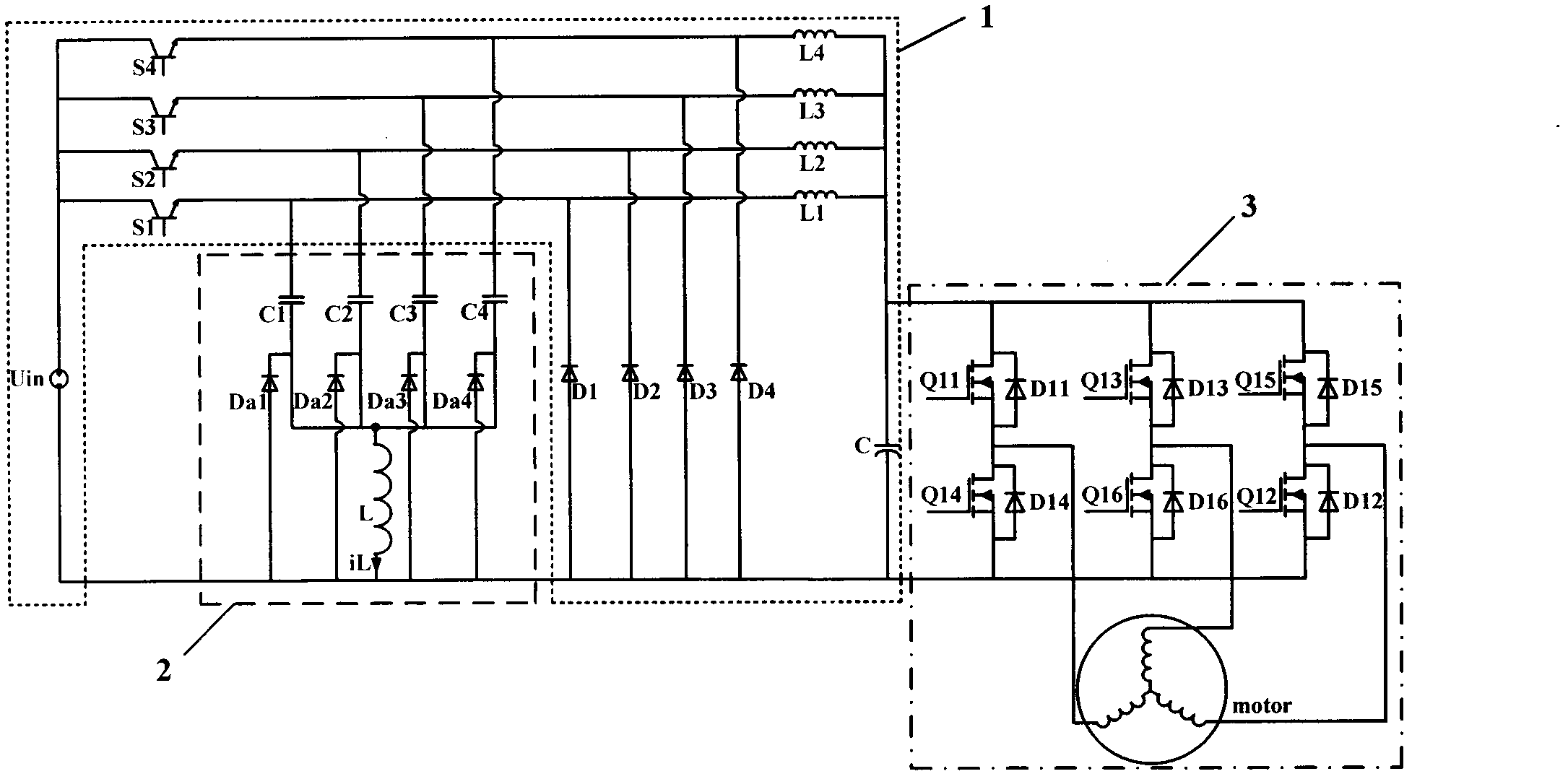
[0013] The circuit topology of this patent is as figure 1 As shown, on the basis of the traditional high-speed motor control circuit, a Buck snubber circuit structure composed of inductance, capacitor and diode is added.

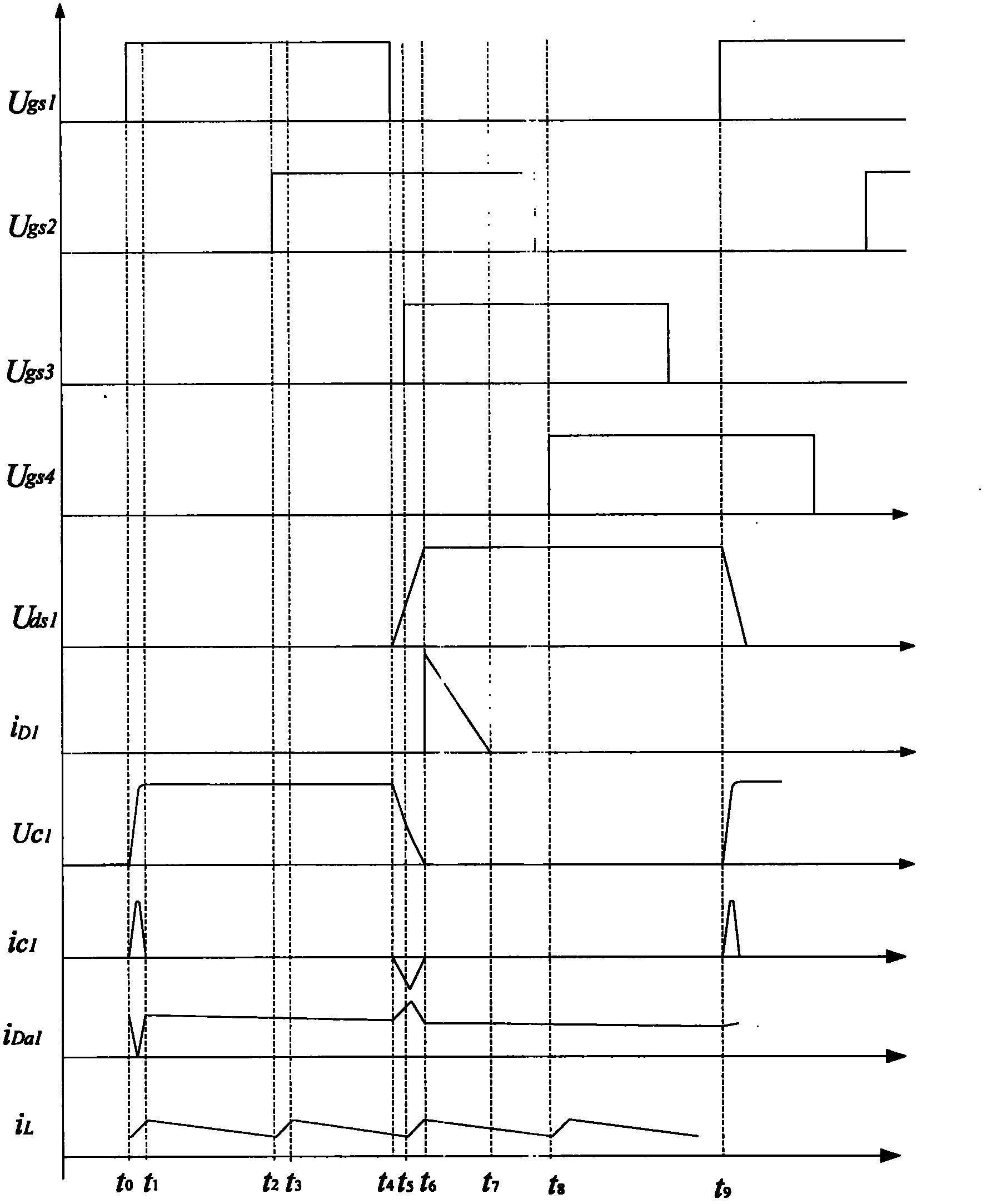
[0014] The main circuit topology is as figure 1 shown. The main body consists of DC input, power switch tube, capacitor and inductor, diode, output capacitor, three-phase inverter bridge, and motor. Its connection method is: power switch S 1 , S 2 , S 3 , S 4 The drain of the input DC power supply U in Connected to the positive input terminal, the gate input is a high-frequency modulation signal, and the source is connected to the inductor L 1 , L 2 , L 3 , L 4 The positive end is connected. Snubber circuit capacitance C 1 、C 2 、C 3 、C 4 respectively connected to the power switch S 1 , S 2 , S 3 , S 4 The source and snubber circuit diodes D a1 、D a2 、D a3 、D a4 between the cathodes of the snubber circuit diode D a1 、D a2 、D a3 、D a...


PUM


Abstract

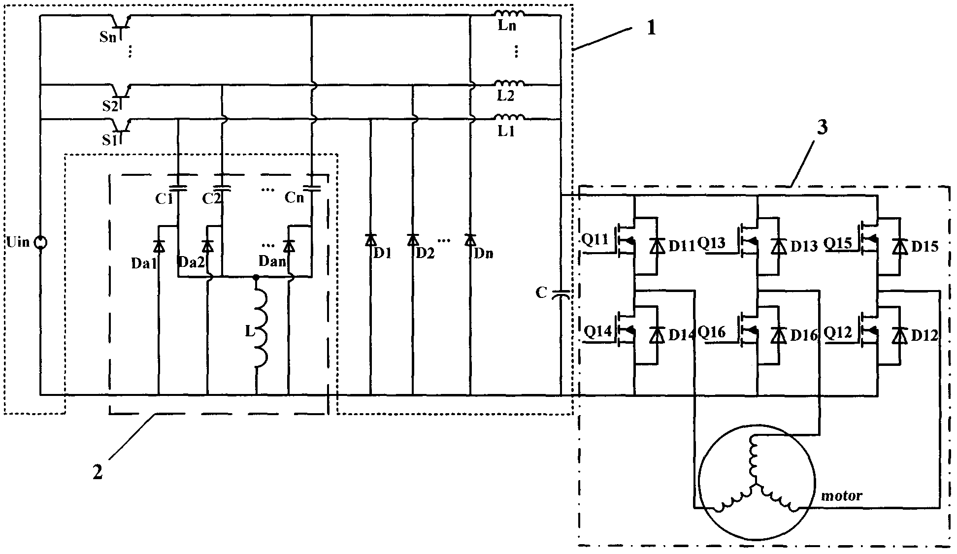
A main circuit of a high-speed superpower motor consists of a front end buck and a rear end bridge type contravariant circuit. A main power pipe of a buck convertor has a high switching frequency, so as to have large loss. The invention provides a front end buck convertor lossless buffer circuit for controlling the high-speed superpower motor. The lossless buffer circuit consisting of a freewheel diode, a capacitor and an inductor is added in the buck convertor. The buck convertor can realize zero-voltage turn-off of a power switching pipe when the power switching pipe performs high frequency chopping. Under super power, a structure with n (n is a natural number larger than 0) buck convertors in parallel is adopted and an interleaving control way is adopted to realize that the lossless buffer circuit with multiple subcircuits shares one inductor and the duty ratio of the switch pipe changes at the ranged of 0.1-0.9, so that output current waves are reduced, voltage and current stress of the switching pipe is reduced, accordingly the power level of a whole circuit is increased, loss of the power switching pipe in the high-speed superpower motor is effectively reduced, and capacitance can be conveniently expanded.

Description

technical field [0001] The invention relates to a non-destructive buffer circuit of a front-end Buck converter used for high-power high-speed motor control, which belongs to the motor control technology. Background technique [0002] With the development of motor design and manufacturing technology, high-power high-speed motors have become one of the research hotspots in the field of electrical engineering at home and abroad because of their high speed, small size and high power density. At present, the control strategy of the conventional motor is: when the motor is running, input direct current and work through the three-phase bridge inverter circuit. However, high-speed motors work at high speeds, and the corresponding switching tubes have high operating frequencies and large losses. In the freewheeling stage under the high-frequency modulation mode, the current is realized through the body diode or integrated diode of the power switch tube, and the loss is large. The us...

Claims


Application Information

Patent Timeline
IPC IPC(8): H02P27/06H02M1/34
Inventor 赵耀张海波邹爱龙陈晨王慧贞
Owner NANJING UNIV OF AERONAUTICS & ASTRONAUTICS
Learn More