Brake system having a multifunction memory device

A brake system and functional technology, applied in the direction of brakes, brake transmission devices, foot-operated starting devices, etc., to achieve the effect of fully self-adaptive idle stroke adjustment and low investment cost

Inactive Publication Date: 2012-08-15
IPGATE
View PDF10 Cites 17 Cited by
  • Summary
  • Abstract
  • Description
  • Claims
  • Application Information

AI Technical Summary

Problems solved by technology

In the extreme case, ie in the event of a brake booster failure on ice, only a small locking press-in, that is to s...

Method used


Image

  • Brake system having a multifunction memory device
  • Brake system having a multifunction memory device
  • Brake system having a multifunction memory device

Examples


Embodiment Construction

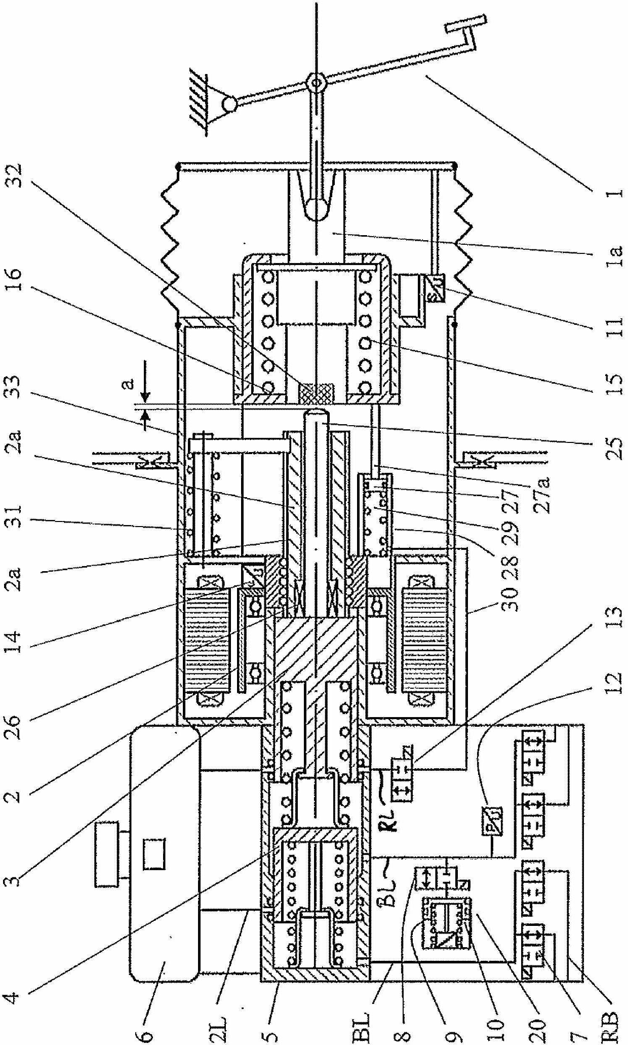
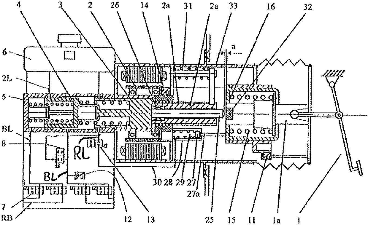
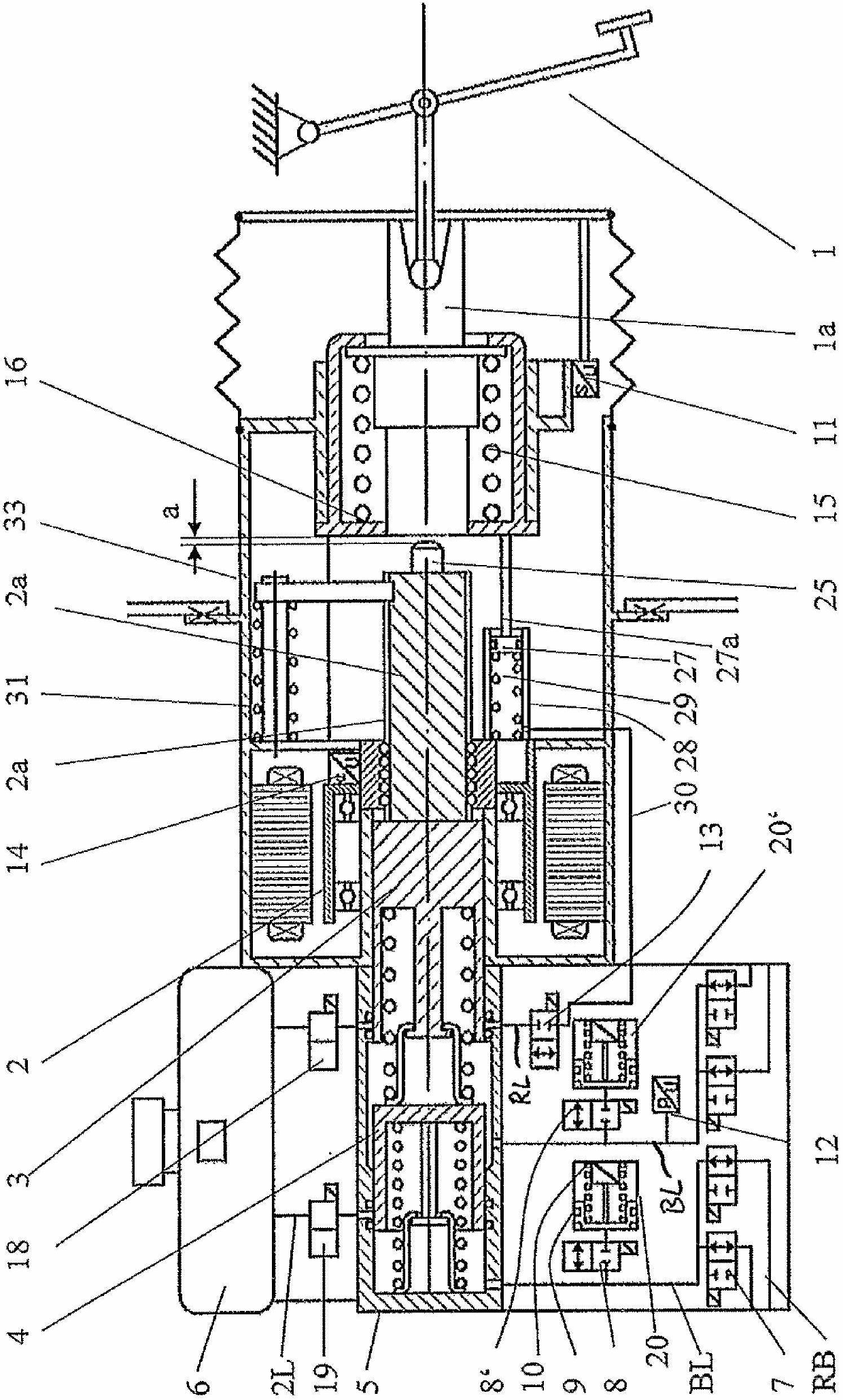
[0037] figure 1 The basic configuration of a highly dynamic motor drive 2 is shown, which moves a piston 3 to vary the pressure in the wheel brakes RB, wherein a wheel brake valve 7 is assigned to each wheel brake RB so that the The brake pressure can be adjusted sequentially, that is to say in multiplex operation. Furthermore, the drive 2 adjusts the piston 3 for the ABS / ESP function. On the electric motor 2 , a tappet piston 3 , which acts hydraulically on the floating piston 4 in a known manner in a tandem master cylinder 5 , is preferably fixedly coupled to the preferably spindle drive 2 a. A 2 / 2 wheel brake valve 7 is arranged in the brake line BL, which, together with the brake booster, realizes the multiplex operation described in WO 2006 / 111393. The brake pedal 1 acts via the pedal pushrod 1 a on a travel simulator spring 16 mounted in the WS housing 15 . This is preferably mounted axially centrally in the housing flange 33 .

[0038] The electric drive can obvious...


PUM


Abstract

The invention relates to a brake system for a motor vehicle, having a master brake cylinder (4, 5), which is driven by an electric drive, wherein a piston plunger (25) and/or a spindle (2a) is in operative connection with a piston (3) of the master brake cylinder (4, 5), having wheel brake valves (7) for selective opening and closing the pressure lines (BL) connecting the wheel brakes (RB) to the master brake cylinder (4, 5), having an actuation device (1), in particular in the form of a brake pedal, that acts on a travel simulator (W), wherein in the event of a malfunction, in particular in the event of failure of the drive (2), the actuation device (1) acts mechanically, in particular by means of the pedal shaft (1a), on the piston plunger (25) to build up pressure in at least one wheel brake, and in normal operation there is a particularly small free travel (ao); between the piston plunger (25) and the actuation device, in particular between the piston plunger (25) and the pedal shaft (1a), having a control device including a brake-by-wire function, which actuates the drive (2) with the piston (3) as well as the wheel brake valves (7), in particular for either simultaneous or consecutive pressure build-up and pressure reduction in the wheel brakes (RB) for the ABS, ESP and/or recuperation functions, wherein the storage tank (6) or a fluid reservoir (20, 20') is used to adjust the magnitude of the free travel (a).

Description

technical field [0001] The invention relates to a brake system according to the preamble of claim 1 . Background technique [0002] A conventional brake booster (BKV) is known as a so-called series booster, in which the pedal stroke is proportional to the piston stroke of the brake master cylinder. Furthermore, there are increasingly systems with travel simulators for brake-by-wire operation in which the above-mentioned relationship no longer applies. Such a system is described in "Electrohydraulic Brakes (EHB)", Brake Handbook 2nd Edition, Vieweg Press, pages 251 and 252 and is not yet optimal in all its functions. [0003] For the various functions of the brake system, the travel simulation system requires an idle travel between the pedal pushrod and the BKV pushrod or the HZ piston, so that no or low pressure is generated, for example, during ABS pressure modulation or during regenerative braking Reaction to the pedal In the case of regenerative braking, despite the gen...

Claims


Application Information

Patent Timeline
IPC IPC(8): B60T7/04B60T8/40B60T13/74
CPCB60T13/745B60T7/042B60T8/4077
Inventor 海因茨·莱贝尔瓦伦丁·翁特尔弗罗纳克里斯蒂安·克格尔施佩格
Owner IPGATE
Why Eureka
Try Eureka