

Large-view-field catadioptric fundus camera optic system
An optical system, catadioptric technology, applied in the optical system field of large field of view catadioptric fundus cameras, can solve the problems of difficult manufacturing and assembly of off-axis retinal objective lens without diopter compensation, small imaging field of view, complex structure, etc. , to reduce the difficulty of processing and manufacturing, reduce the difficulty of assembly and adjustment, and solve the effect of large field of view
- Summary
- Abstract
- Description
- Claims
- Application Information
AI Technical Summary
Problems solved by technology
Method used
Image

Examples
specific Embodiment approach 1
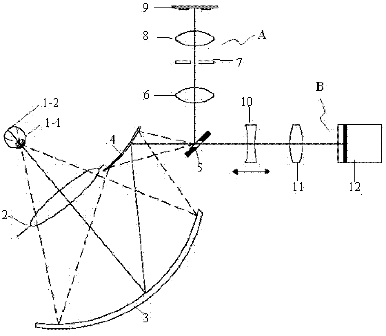
[0015] to combine figure 1 To describe this embodiment, figure 1 It is a schematic diagram of the optical principle of a large field of view catadioptric fundus camera optical system of the present invention, including an optical model 1 of the human eye, a clear aperture 2, a reflective retinal objective lens primary mirror 3, and a reflective retinal objective lens secondary Mirror 4, hollow reflector 5 (the hollow part is also the aperture diaphragm of the imaging system), refractive illumination relay mirror group 6, illumination diaphragm 7, refractive illumination condenser lens group 8, light source 9, refractive focusing lens group 10. A refraction focusing imaging group 11 and a camera 12. The present invention adopts coaxial illumination, the illumination light path A and the imaging light path B share the clear aperture 2 of the omentum objective lens, the main mirror 3 of the reflection type omentum objective lens and the secondary mirror 4 of the reflection type ...
specific Embodiment approach 2
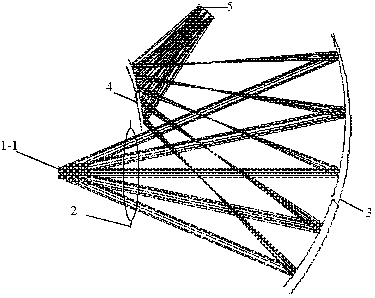
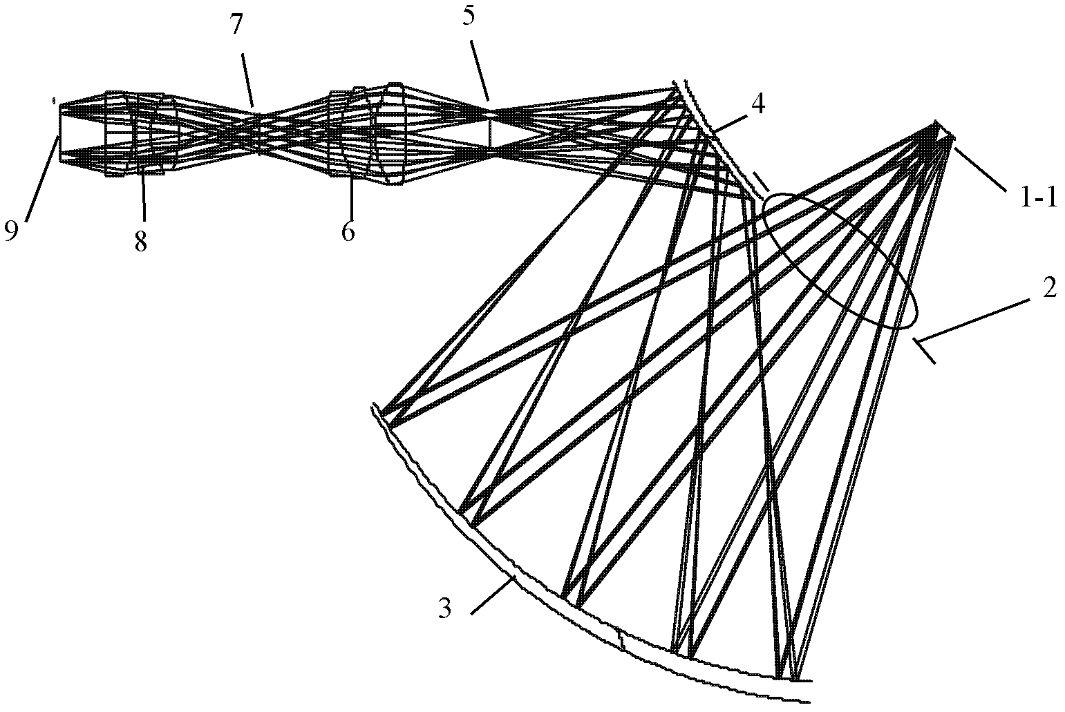
[0020] to combine figure 2 , image 3 and Figure 4 Description of this embodiment
[0021] figure 2 It is the optical structure diagram of the used omentum objective lens of the present embodiment, figure 2 The retinal objective in the image 3 light path and Figure 4 The common part of the imaging light path, the pupil 1-1 (object side), the clear aperture 2, the reflective omentum objective primary mirror 3 and the reflective omentum objective secondary mirror 4, and the hollow mirror 5 (image side) are on the same optical axis (folded optical axis) placed sequentially. Its magnification is 1.5, the pupil (object space) 1-1 is 6mm, the image space 5 is 9mm, and the front working distance is 48mm.
[0022] The structural parameters of reflective omentum objective lens main mirror, reflective omentum objective lens secondary mirror and hollow reflector are provided below in the present embodiment:
[0023] Table 1
[0024]
[0025] Table 2
[0026]
[0027...
PUM
 Abstract
Description
Claims
Application Information