Manufacturing method of high-strength end mill cutting edge and double-front-angle end mill

A production method and end mill technology, which are applied in milling cutters, manufacturing tools, milling machine equipment, etc., can solve the problems of unsatisfactory end mill production technology, reduced surface finish of parts, complicated processing technology, etc., so as to improve the processing finish, The effect of low production cost and simple processing technology

Inactive Publication Date: 2012-08-22
XINAN TOOLS GUIZHOU PROV
View PDF5 Cites 2 Cited by
  • Summary
  • Abstract
  • Description
  • Claims
  • Application Information

AI Technical Summary

Problems solved by technology

[0002] During the metal cutting process, the cutting layer is deformed through the extrusion of the cutting edge, and the chips flow along the rake face to the spiral chip flute for removal, and the most likely to occur The damaged and worn parts are generally on the cutting edge and the rake face closer to the edge. At present, the shape of the cutting edge on traditional end milling tools is mainly determined by the rake angle and the rear angle. After the rake angle and relief angle of the cutting edge of the milling cutter are determined, the strength of the cutting edge of the end mill is also determined under the same material and the same processing

Method used


Image

  • Manufacturing method of high-strength end mill cutting edge and double-front-angle end mill
  • Manufacturing method of high-strength end mill cutting edge and double-front-angle end mill
  • Manufacturing method of high-strength end mill cutting edge and double-front-angle end mill

Examples


Embodiment Construction

[0017] The present invention will be further described in detail below in conjunction with the accompanying drawings and embodiments.

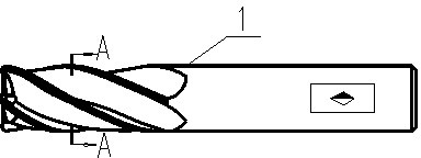
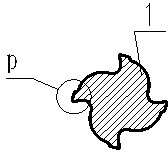
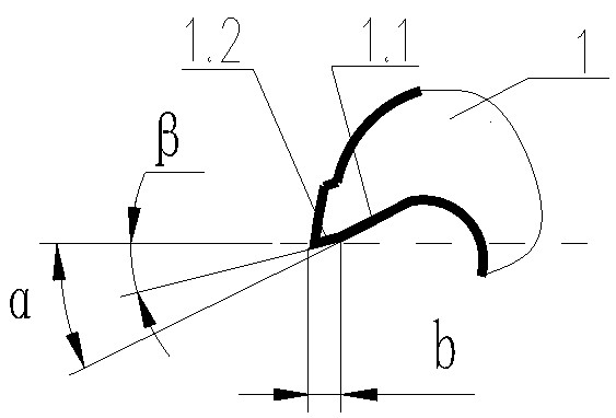
[0018] Embodiments of the present invention: when adopting the manufacturing method of a kind of high-strength end mill cutting edge of the present invention to make end mill 1, its used end mill material and manufacturing process are all the same as the prior art, but in manufacturing equipment For the cutting edge of the end mill 1 with spiral grooves, the main rake angle 1.1 is first made on the cutting edge of the end mill 1, and then a secondary rake angle 1.2 is made on the main rake angle 1.1, so that the main rake angle The main rake angle α of 1.1 is greater than the sub-rake angle β of the sub-rake 1.2.

[0019] The structural representation of a kind of double rake angle end mill of the present invention constructed according to the above-mentioned method is as Figure 1 ~ Figure 3 As shown, the double-rake angle end mill inc...


PUM


Abstract

The invention discloses a manufacturing method of a high-strength end mill cutting edge and a double-front-angle end mill. To manufacture a cutting edge of an end mill (1) with a spiral groove, a main front angle (1.1) is firstly manufactured on the cutting edge of the end mill (1), an auxiliary front angle (1.2) is then manufactured on the main front angle (1.1), and the angle (alpha) of the main front angle (1.1) is greater than the angle (beta) of the auxiliary front angle (1.2). The cutting edge disclosed by the invention not only can effectively improve the end mill cutting edge strength and the processing fineness, but also has the advantages of simple processing technology, relatively low manufacturing cost and relatively long service life.

Description

technical field [0001] The invention relates to a method for manufacturing a high-strength end mill cutting edge and a double rake end mill, belonging to the technical field of end mill manufacture. Background technique [0002] In the process of metal cutting, the cutting layer is deformed by the extrusion of the cutting edge, and the chips flow along the rake face to the spiral chip flute to be removed, and the parts that are most prone to damage and wear are generally at the cutting edge and the distance from the cutting edge. The closest is the rake face. At present, the shape of the cutting edge on the traditional end mill is mainly determined by the rake angle and the relief angle. When the rake angle and the relief angle of the cutting edge of the end mill are determined, in the same In the case of the same material and processing technology, the strength of the cutting edge of the end mill is also determined. In order to enhance the strength of the cutting edge of th...

Claims


Application Information

Patent Timeline
IPC IPC(8): B23C5/10B23P15/34
Inventor 杨秀章冷海军
Owner XINAN TOOLS GUIZHOU PROV
Why Eureka
Try Eureka