

Stand-by circuit
A standby circuit and electrical connection technology, applied in the field of electronics, can solve the problems of waste of electric energy, large loss of transformers, and inability to achieve
- Summary
- Abstract
- Description
- Claims
- Application Information
AI Technical Summary
Problems solved by technology
Method used
Image

Examples
Embodiment Construction
[0025] The present invention will be described in further detail below in conjunction with the accompanying drawings and specific embodiments.
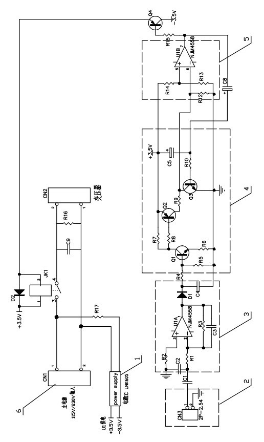
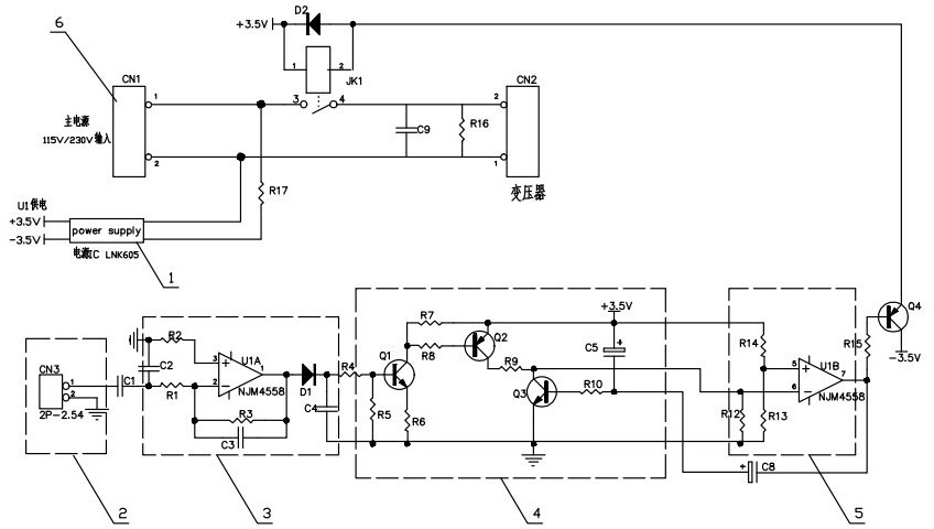
[0026] Depend on figure 1 As can be seen from the schematic circuit diagram of the standby circuit of the present invention, it is made up of the following parts:
[0027] Voltage conversion unit 1, signal detection sampling unit 2, signal amplification unit 3, switch control unit 4, signal comparison unit 5, transistor Q4 and relay JK1;
[0028] The input end of the voltage conversion unit 1 is electrically connected to the main power supply 6, and the output end outputs a DC voltage. The signal detection sampling unit 2, the signal amplification unit 3, the switch control unit 4, and the signal comparison unit 5 are electrically connected in turn, and the output of the signal comparison unit 5 terminal is electrically connected to the base of the transistor Q4, and the emitter of the transistor Q4 is electrically connected to the p...
PUM
 Abstract
Description
Claims
Application Information