Configurable digital-analog phase locked loop

A digital simulation, phase-locked loop technology, applied in the automatic control of power, electrical components, etc.

Active Publication Date: 2012-08-22
QUALCOMM INC
View PDF4 Cites 10 Cited by
  • Summary
  • Abstract
  • Description
  • Claims
  • Application Information

AI Technical Summary

Problems solved by technology

Unfortunately, these PLLs also have some disadvantages

Method used


Image

  • Configurable digital-analog phase locked loop
  • Configurable digital-analog phase locked loop
  • Configurable digital-analog phase locked loop

Examples


Embodiment Construction

[0021] The word "exemplary" is used herein to mean "serving as an example, instance, or illustration." Any embodiment described herein as "exemplary" is not necessarily to be construed as preferred or advantageous over other embodiments.

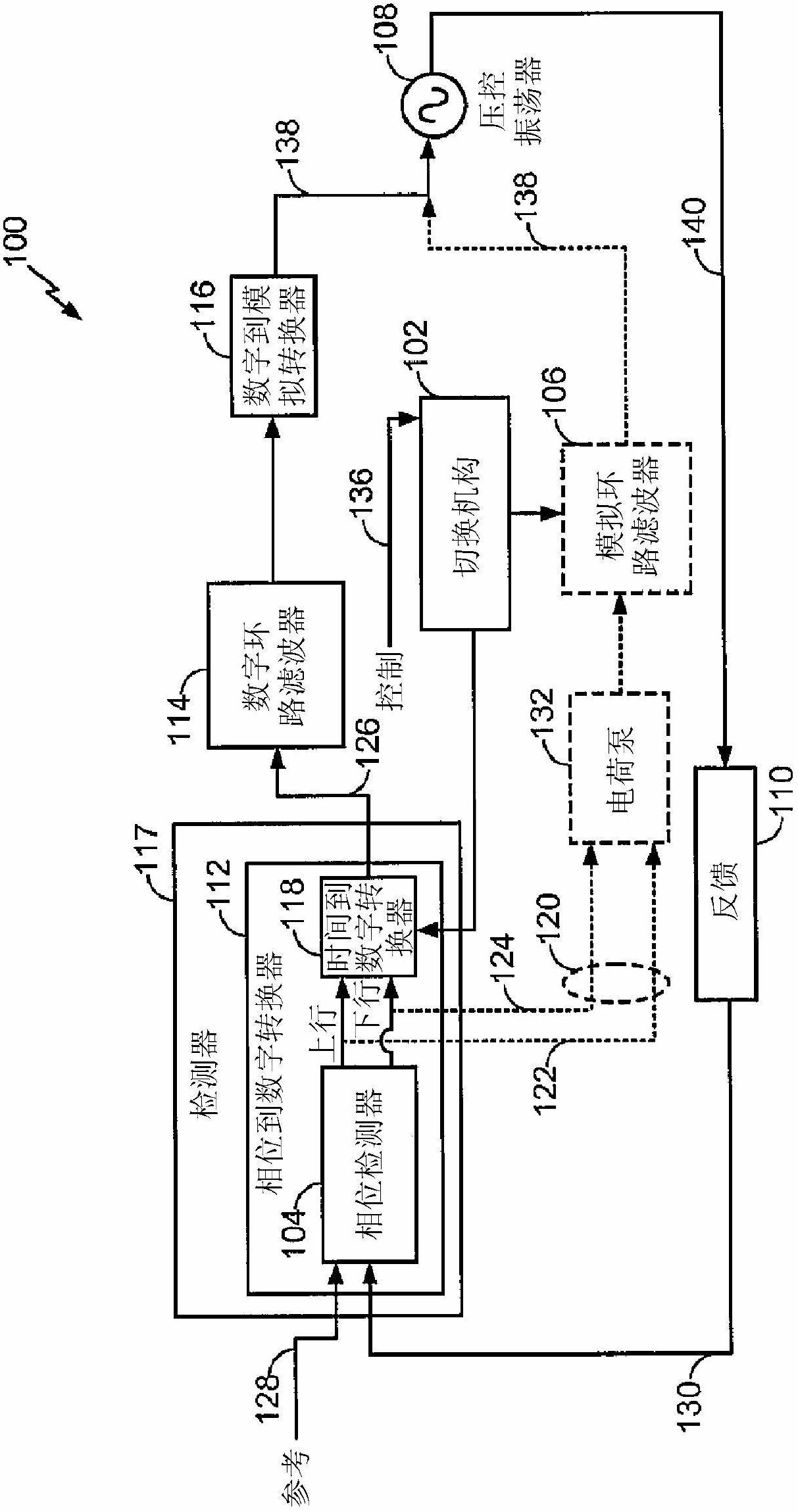
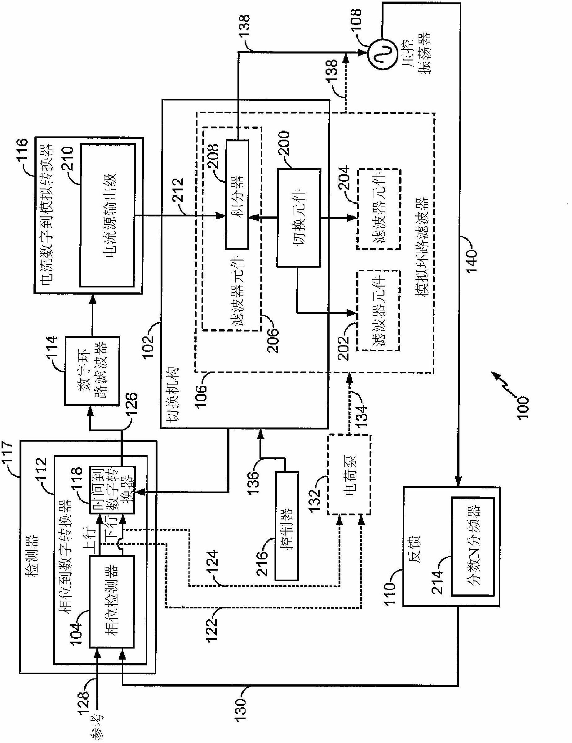
[0022] figure 1 is a block diagram of a configurable analog-to-digital phase locked loop device (PLL device) 100 according to an exemplary embodiment of the present invention. Any suitable combination of devices, circuits, and / or codes may be used to implement the figure 1 The function block in question. Accordingly, the functions of the blocks may be implemented in hardware, software and / or firmware. The functions of several blocks may be performed by a single circuit or device, and the functions described as being performed by a single block may be performed by several devices or circuits.

[0023] The PLL device includes a switching mechanism 102 that configures the PLL device 100 as an analog PLL, or as a hybrid digital-analog PLL th...


PUM


Abstract

A phase locked loop (PLL) device is configurable in an analog phase locked loop and a hybrid analog-digital phase locked loop. In an analog mode, at least a phase detector, an analog loop filter, and a voltage controlled oscillator (VCO), are connected to form an analog loop. In a digital mode, at least the phase detector, the voltage controlled oscillator (VCO), a time to digital converter (TDC), a digital loop filter and a digital to analog converter (DAC) are connected to form the hybrid digital-analog loop.

Description

technical field [0001] The present invention relates generally to phase locked loops, and more particularly to hybrid analog-digital phase locked loops. Background technique [0002] A phase locked loop (PLL) generates a signal relative to a reference signal. A phase locked loop circuit adjusts the frequency of the PLL output signal based on the phase and / or frequency difference between the reference signal and the PLL output signal. The frequency of the output signal is increased or decreased based on the difference. Therefore, a phase locked loop is a control system that uses negative feedback. Phase locked loops are used in electronic devices such as radios, telecommunications circuits, and computers, among other devices. [0003] PLLs often use a resonantly tuned voltage-controlled oscillator (VCO) to generate the PLL output signal. A resonant tuned VCO often includes a capacitive device and a resonant inductor-capacitor (LC) circuit. The capacitive device typically...

Claims


Application Information

Patent Timeline
IPC IPC(8): H03L7/089H03L7/093
CPCH03L7/089H03L7/0891H03L7/093H03L7/085
Inventor 杰里米·D·邓恩沃思加里·J·巴兰坦布尚·S·阿苏瑞
Owner QUALCOMM INC
Why Eureka
Try Eureka