Temperature compensation method for denoising fiber-optic gyroscope on basis of time series analysis

A time series analysis, fiber optic gyroscope technology, applied in aerospace navigation and aviation fields, can solve the problem of fiber optic gyroscope zero offset drift, affecting the thermal equilibrium state of the gyroscope, etc.

Inactive Publication Date: 2012-08-29
BEIHANG UNIV
View PDF7 Cites 65 Cited by
  • Summary
  • Abstract
  • Description
  • Claims
  • Application Information

AI Technical Summary

Problems solved by technology

The performance of the optical components in the fiber optic gyroscope changes with temperature, and the non-linear change of the internal temperature field of the gyroscope caused by

Method used


Image

  • Temperature compensation method for denoising fiber-optic gyroscope on basis of time series analysis
  • Temperature compensation method for denoising fiber-optic gyroscope on basis of time series analysis
  • Temperature compensation method for denoising fiber-optic gyroscope on basis of time series analysis

Examples


Embodiment Construction

[0152] The present invention will be further described in detail below in conjunction with the accompanying drawings.

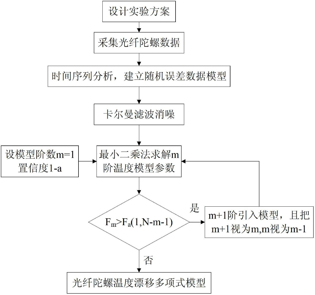
[0153] see figure 2 , The present invention is a method for temperature compensation of fiber optic gyroscope based on time series analysis and denoising. The specific implementation steps of the method are as follows:

[0154] Step 1: Design an experiment plan, conduct a fixed-point temperature experiment on the fiber optic gyroscope, and collect data. The temperature experiment adopts a static test, in which the X, Y, and Z-axis fiber optic gyroscopes point east, north, and sky respectively. In order to study the effect of temperature on the zero offset of the fiber optic gyroscope, the ambient temperature of -30℃, -20℃, -10℃, 0℃, 10℃, 20℃, 30℃, 40℃, 50℃, 60℃ (or Determine the selected temperature point according to the working temperature), and perform high and low temperature tests on the fiber optic gyroscope. After holding each temperature for two hours, ...


PUM


Abstract

A temperature compensation method for denoising a fiber-optic gyroscope on the basis of time series analysis comprises four steps of: step 1, designing an experimental scheme, performing fixed point low and high temperature testing experiment on the fiber-optic gyroscope, and utilizing acquisition software for data acquisition; step 2, performing time series analysis on the zero offset data of the gyroscope, and establishing the mathematical model of the random error of the fiber-optic gyroscope; step 3, adopting a kalman filtering algorithm to filter random noise in the zero offset data of the fiber-optic gyroscope; and step 4, utilizing the data which is de-noised by the kalman filtering to identify the model structure of the temperature shift error of the fiber-optic gyroscope, and calculating the parameters of the identified model. The method establishes the multinomial model of the static temperature shift error of the fiber-optic gyroscope through time series analysis, kalman filtering denoising treatment and identification of the temperature shift error model structure and parameters. The method completely meets the real-time compensation requirement on the project, and has a better practicable value and a wide application prospect in the technical field of aerospace navigation.

Description

(1) Technical field [0001] The present invention relates to a fiber optic gyroscope temperature compensation method based on time series analysis and denoising, which elaborates the method of time series analysis to eliminate noise and temperature compensation. This relationship can be accurately identified, an accurate model can be established, and the effectiveness of temperature compensation can be improved. This technology belongs to the field of aviation and aerospace navigation technology. (2) Background technology [0002] As a new type of inertial angular velocity sensor that is developing extremely rapidly, fiber optic gyroscope has its unique technical and performance advantages, such as all-solid-state structure, high reliability, long life; fast start-up speed, short response time; large measurement range and wide dynamic range ; Anti-shock, vibration, chemical corrosion resistance; small size, light weight, low cost; suitable for mass production, etc., have bee...

Claims


Application Information

Patent Timeline
IPC IPC(8): G01C25/00G01C19/72
Inventor 晁代宏宋凝芳周小红王振飞宋来亮
Owner BEIHANG UNIV
Why Eureka
Try Eureka