Bearing load identification method based on strain signals of three cross sections of rotating shaft

A technology of bearing load and identification method, which is applied in the measurement of elastic deformation force by measuring gauges, etc., can solve the problems of easily touching the upper bearing shell and large result error, and achieves small modeling error, simple structure, and testing workload. small effect

Inactive Publication Date: 2012-08-29
YUN NAN ELECTRIC TEST & RES INST GRP CO LTD ELECTRIC INST +1
View PDF2 Cites 10 Cited by
  • Summary
  • Abstract
  • Description
  • Claims
  • Application Information

AI Technical Summary

Problems solved by technology

However, since the bearing clearance is usually very small, mostly between 0.2mm and 0.5mm, it is easy to touch the upper bearing pad during jacking, thus generati

Method used


Image

  • Bearing load identification method based on strain signals of three cross sections of rotating shaft
  • Bearing load identification method based on strain signals of three cross sections of rotating shaft
  • Bearing load identification method based on strain signals of three cross sections of rotating shaft

Examples


Embodiment Construction

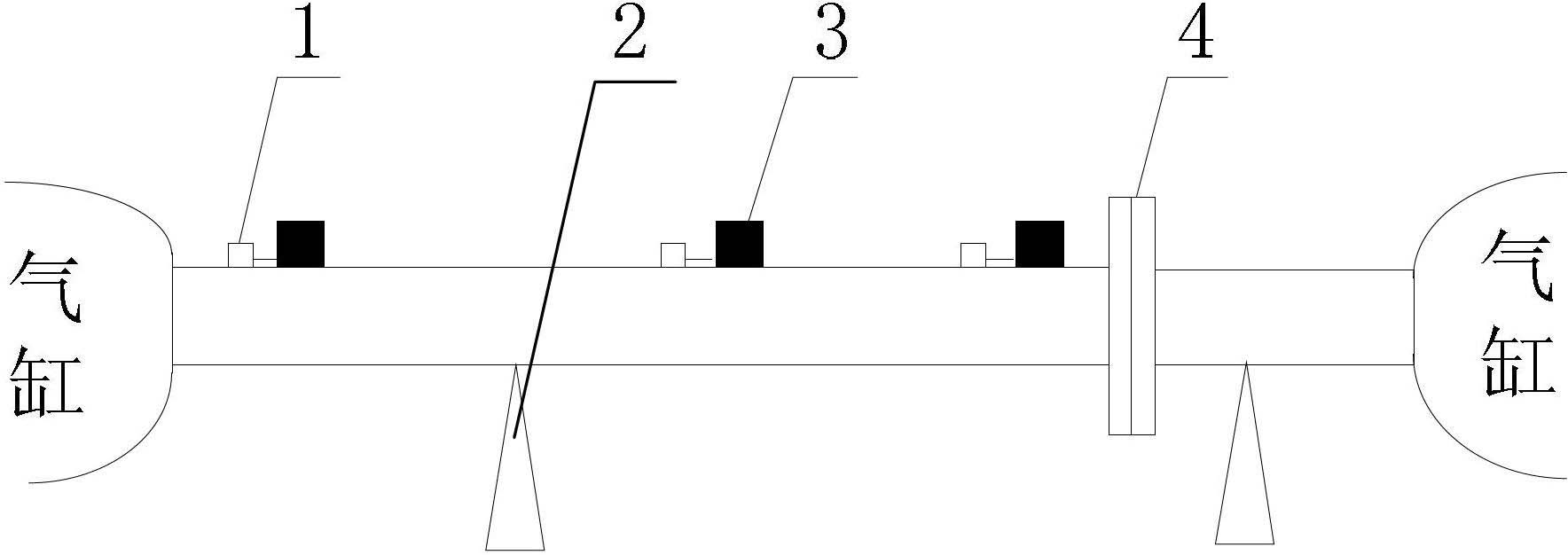
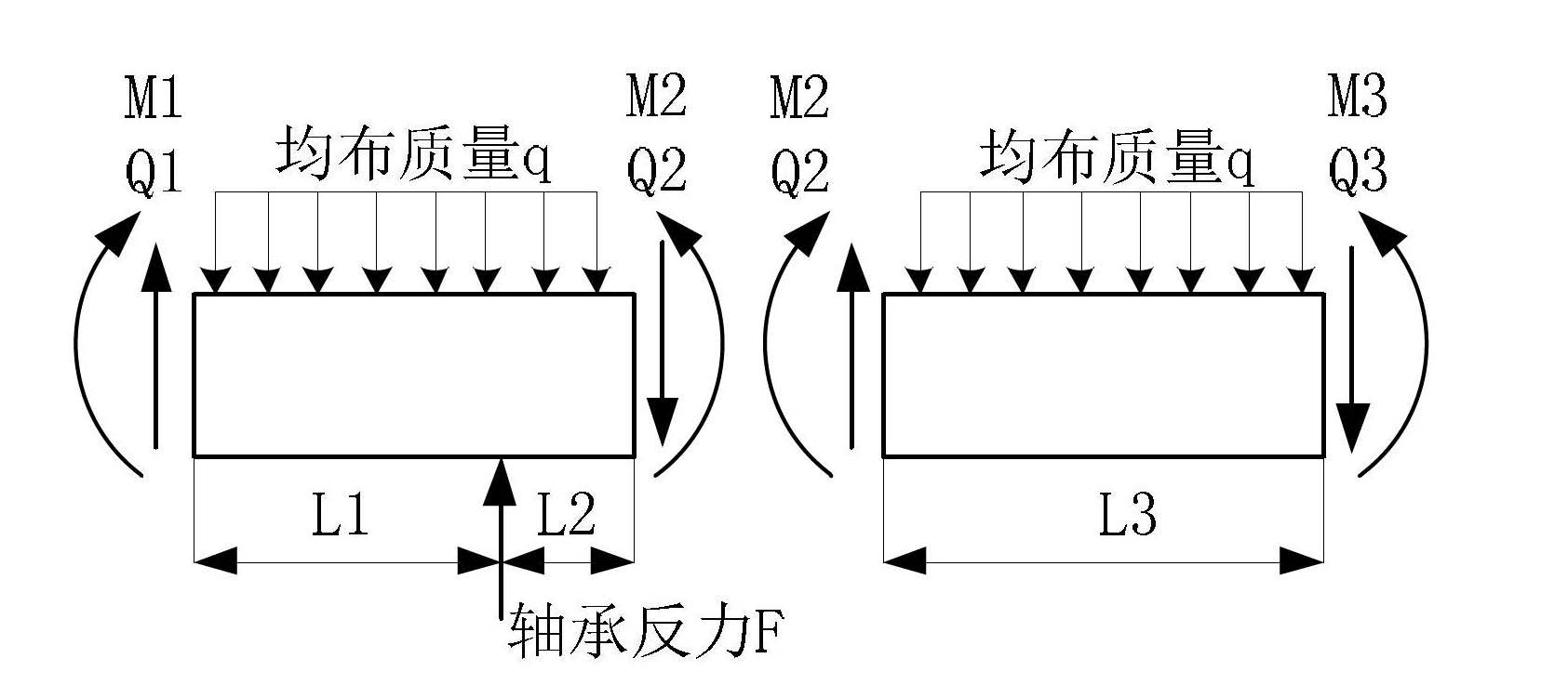
[0031] This embodiment is based on figure 1 Taking a certain bearing to be tested as an example, the three-section load identification analysis is carried out. refer to Figure 2-4 .

[0032] The bearing load identification analysis method based on the three-section strain signal of the rotating shaft involved in this embodiment is:

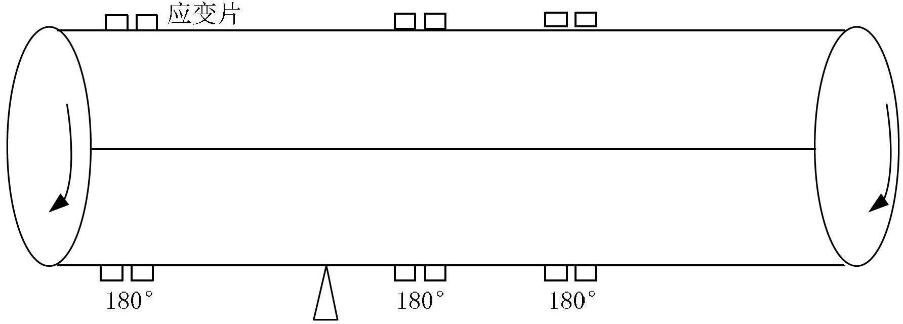
[0033] (1) Paste a set of strain gauges on three different sections at both ends of the bearing to be tested, and these three sections cannot be located on the same side of the bearing. Such as figure 1 shown. The strain gauges at each section adopt the full-bridge layout mode, that is, two strain gauges are arranged at 0° and 180° on the circumferential surface, and the four strain gauges on the cross-section form a group to form a full-bridge test mode, such as figure 2 shown.

[0034] (2) Rotate the rotor, measure the output signal of the strain gauge at 0° and 180° during the rotation of the shaft; in order to eliminate the error, the ...


PUM


Abstract

The invention discloses a bearing load identification method based on strain signals of three cross sections of a rotating shaft. According to the invention, by testing the strain signals at the three cross sections at two ends of a bearing, the bearing load is identified. The invention has the advantages as follows: (1), compared with the traditional strain method, the method provided by the invention adopts a local modeling method, so that the problems of strain measurement error accumulation, transmission and divergence are avoided; and compared with the traditional integral modeling method, the bearing load identification method has the advantages that the structure of the shaft section nearby the bearing is simple, a mathematical model can be built up more accurately, and the modeling error is less; (2), the testing work load is small; strain testing points can be arranged nearby the bearing, and point distribution at the middle part of the rotating shaft, which requires opening the cylinder, is not required; and (3), the bearing load can be tested under a low-speed dynamic state, so that the actual load condition can be reflected more truly.

Description

technical field [0001] The invention is applicable to the field of state monitoring and fault diagnosis of rotating machine bearings, and its main application scope includes: steam turbine generating sets, gas turbine generating sets and other types of power rotating machines supported by bearings. Background technique [0002] Bearings are important components of various types of rotating machinery, which play an important role in supporting the rotor and are crucial to the safe operation of the unit. A large number of theoretical studies and engineering practices have shown that the load on the bearing directly affects the working condition of the bearing. If the bearing load is too heavy, the bearing is prone to faults such as high tile temperature, cracking of black metal, and tile rolling; if the bearing load is too light, it is prone to failures such as oil film whirl and oil film oscillation. In both cases, the bearings will generate large vibrations, which will affe...

Claims


Application Information

Patent Timeline
IPC IPC(8): G01L1/04
Inventor 李燕勇董川彭斌
Owner YUN NAN ELECTRIC TEST & RES INST GRP CO LTD ELECTRIC INST
Why Eureka
Try Eureka