Manufacturing method for FinFETs (fin field effect transistors)

A field-effect transistor and fin-type technology, which is applied in the field of preparation of bulk silicon fin-type field effect transistors, can solve the problems of large leakage current and unsatisfactory SCE effect suppression effect, so as to reduce the dependence of equipment and overcome self-heating. Effects and floating body effects, easy-to-implement effects

Active Publication Date: 2012-08-29
SOI MICRO CO LTD
View PDF4 Cites 19 Cited by
  • Summary
  • Abstract
  • Description
  • Claims
  • Application Information

AI Technical Summary

Problems solved by technology

However, the general Bulk FinFET structure device still has the following disadvantages compared with the SOI FinFET device: the SCE effect suppression effect is not very ideal; the leakage current path is still formed in the fin at the bottom of the channel, resulting in a large leakage current

Method used


Image

  • Manufacturing method for FinFETs (fin field effect transistors)
  • Manufacturing method for FinFETs (fin field effect transistors)
  • Manufacturing method for FinFETs (fin field effect transistors)

Examples


Embodiment Construction

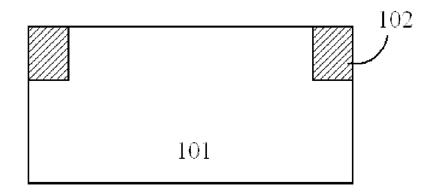
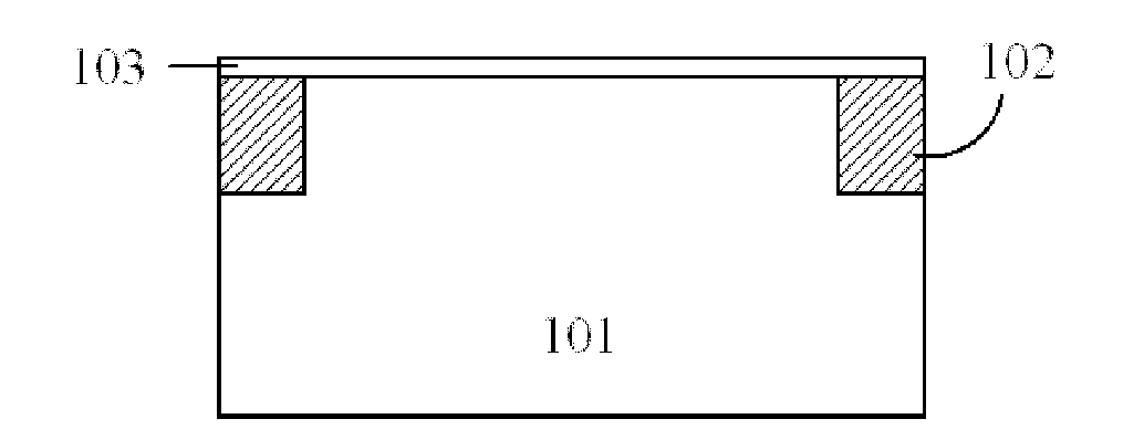
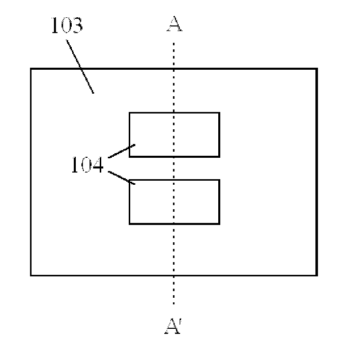
[0026] Hereinafter, the present invention is described by means of specific embodiments shown in the drawings. It should be understood, however, that these descriptions are exemplary only and are not intended to limit the scope of the present invention. Also, in the following description, descriptions of well-known structures and techniques are omitted to avoid unnecessarily obscuring the concept of the present invention.

[0027] A schematic diagram of a layer structure according to an embodiment of the invention is shown in the drawing. The figures are not drawn to scale, with certain details exaggerated and possibly omitted for clarity. The shapes of the various regions and layers shown in the figure, as well as their relative sizes and positional relationships are only exemplary, and may deviate due to manufacturing tolerances or technical limitations in practice, and those skilled in the art will Regions / layers with different shapes, sizes, and relative positions can be...


PUM


Abstract

The invention discloses a manufacturing method for FinFETs (fin field effect transistors), which includes the following steps: forming Omega-shaped fins on a semiconductor substrate; forming grid stacking structures at the tops and on the lateral surfaces of the Omega-shaped fins; forming source/leakage structures in the Omega-shaped fins on the two sides of the grid stacking structures; and performing metallization, wherein except that the bottoms of the Omega-shaped fins are connected with the semiconductor substrate through a narrower silicon strip, the other parts of the grid stacking structures are separated from the semiconductor substrate through a separation dielectric layer. The manufacturing method provided by the invention eliminates the self-heating effect and the floating body effect existing in an SOI device, has lower cost, overcomes the defects that the common bulk FinFET has big creepage current and better SCE (short-channel effect), is excellently compatible with the CMOS (complementary metal oxide semiconductor) plane technology, and is simple to integrate.

Description

technical field [0001] The invention belongs to the technical field of semiconductors, in particular to a method for preparing a bulk silicon fin field effect transistor. Background technique [0002] As the integrated circuit industry continues to develop in accordance with Moore's law, the feature size of CMOS devices continues to shrink, and planar bulk silicon CMOS devices have encountered severe challenges. In order to overcome these problems, various new structural devices have emerged as the times require. Among many new structure devices, Fin Field Effect Transistor (FinFET) is considered to be one of the new structure devices most likely to replace planar bulk silicon CMOS devices, and has become an international research hotspot. [0003] FinFET structure devices are mainly prepared on SOI substrates in the early stage, and the process is simpler than that of bulk silicon substrates. However, SOI FinFET has disadvantages such as high manufacturing cost, poor heat...

Claims


Application Information

Patent Timeline
Patent Type & Authority Applications(China)
IPC IPC(8): H01L21/336
CPCH01L29/66795
Inventor 周华杰徐秋霞宋毅
Owner SOI MICRO CO LTD
Why Eureka
Try Eureka