Conveying device

A technology of conveying device and conveying direction, which is applied in the direction of conveyors, conveyor objects, transportation and packaging, etc., which can solve problems such as high weight, difficulty in conveying and installing conveyors, unsatisfactory vibration and vibration damping characteristics, etc., to achieve Efficiency and low-vibration conveying process High, simple construction effect

Inactive Publication Date: 2012-09-05
HOMAG HOLZBEARBEITUNGSSYST
View PDF8 Cites 0 Cited by
  • Summary
  • Abstract
  • Description
  • Claims
  • Application Information

AI Technical Summary

Problems solved by technology

[0004] However, it has been shown that the vibration and vibration damping properties of load-bearing structures made of steel or other metals are often unsatisfactory
In addition, the disadvantage of steel construction is the extremely high weight, and this makes both conveying and installation of such conveyors difficult
Last but not least, the production of load-bearing structures from steel requires a high energy input and this is not ideal from an environmental point of view

Method used


Image

  • Conveying device
  • Conveying device
  • Conveying device

Examples


Embodiment Construction

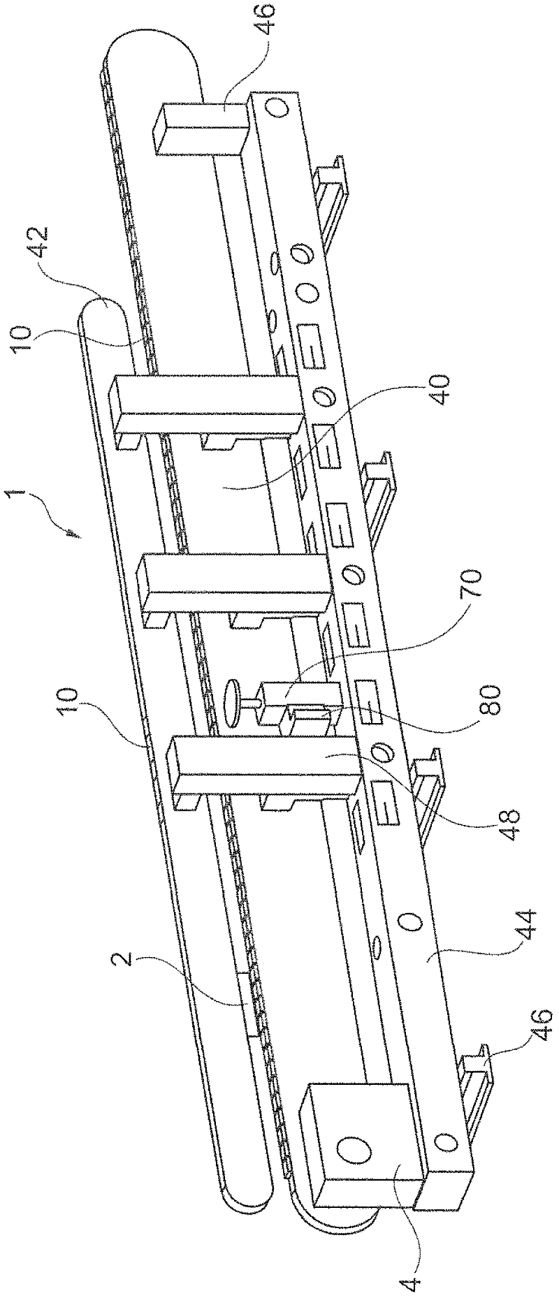
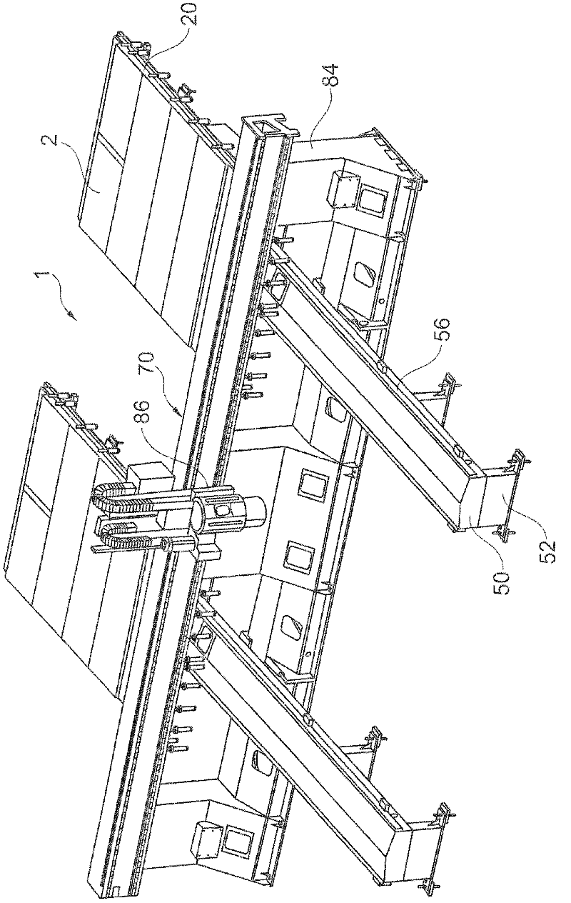
[0021] The following preferred embodiments of the present invention will be described in detail below with reference to the accompanying drawings. exist figure 1 A schematic perspective view of a device 1 for conveying workpieces 2 in a conveying direction and for synchronously processing them is shown schematically in . It should be pointed out here that the plant 1 shown as plant 1 can be designed not only as a pure conveying plant, but also as a combined conveying and processing plant. Like the other devices described below, the device 1 here is preferably used for conveying and optionally processing workpieces at least partially made of wood, wood, plastic or the like, as in the field of the furniture and component industry, for example widely used.

[0022] exist figure 1 The apparatus 1 shown in , initially comprises a conveying device 10 which in this embodiment is designed as an infinitely rotating element in the form of a so-called magnetic chain. It should be not...


PUM


Abstract

The invention provides a device (1) used for conveying a workpiece (2) along the conveying direction and preferably used for machining the workpiece (2). The device (1) has at least one movable or rotating conveying unit (10, 20, 30) through which the workpieces can be taken directly or indirectly in the conveying direction. The device has a support structure (40...; 50...; 60...; 70; 80), and the support structure (40...; 50...; 60...; 70; 80) is adapted to disperse support forces and reaction forces of the conveying unit (10, 20, 30). The sections of support structure (40...; 50...; 60...; 70; 80) are at least partially made of cement-concrete such as ultra high performance concrete (UHPC) and / or fiber reinforced concrete, so that tensile strength of support structure is set at least 15 MPa and water / binder ratio of 0.30 to the maximum.

Description

technical field [0001] The invention relates to a device for conveying workpieces in a conveying direction and preferably also for processing workpieces, comprising: at least one movable or rotating conveying device, on which workpieces can be held directly or indirectly in order to move along The conveying direction conveys the workpiece; and the load-bearing structure is arranged to distribute, ie absorb and transmit, the support or reaction forces of the at least one conveying device. Background technique [0002] Conveyors of the aforementioned type are widely used, for example, in the processing and handling of workpieces. Here, on the one hand, in the context of pure transport, the conveyor can be used to move the workpieces only in one transport direction to move the workpieces, for example from a first processing tool to a second processing tool or within a storage device. On the other hand, a general conveyor can also be part of a processing plant and be used in th...

Claims


Application Information

Patent Timeline
Patent Type & Authority Applications(China)
IPC IPC(8): B65G21/00B65G17/30B65G41/00
CPCB23Q1/015B23Q7/03B65G21/00
Inventor 马丁·格林格尔约阿希姆·费切尔
Owner HOMAG HOLZBEARBEITUNGSSYST
Why Eureka
Try Eureka