Method for determining soot mass stored with a particulate filter

A particle filter and smoke particle technology, applied in the direction of machines/engines, electronic control of exhaust treatment devices, diagnostic devices of exhaust treatment devices, etc., can solve the problems of adding pressure sensors and increasing system costs, and achieve reduction cost effect

Active Publication Date: 2012-09-05
FORD GLOBAL TECH LLC
View PDF7 Cites 11 Cited by
  • Summary
  • Abstract
  • Description
  • Claims
  • Application Information

AI Technical Summary

Problems solved by technology

While it is possible to determine the pressure differential within the exhaust system, adding a pressure sensor to the exhaust s

Method used


Image

  • Method for determining soot mass stored with a particulate filter
  • Method for determining soot mass stored with a particulate filter
  • Method for determining soot mass stored with a particulate filter

Examples


Embodiment Construction

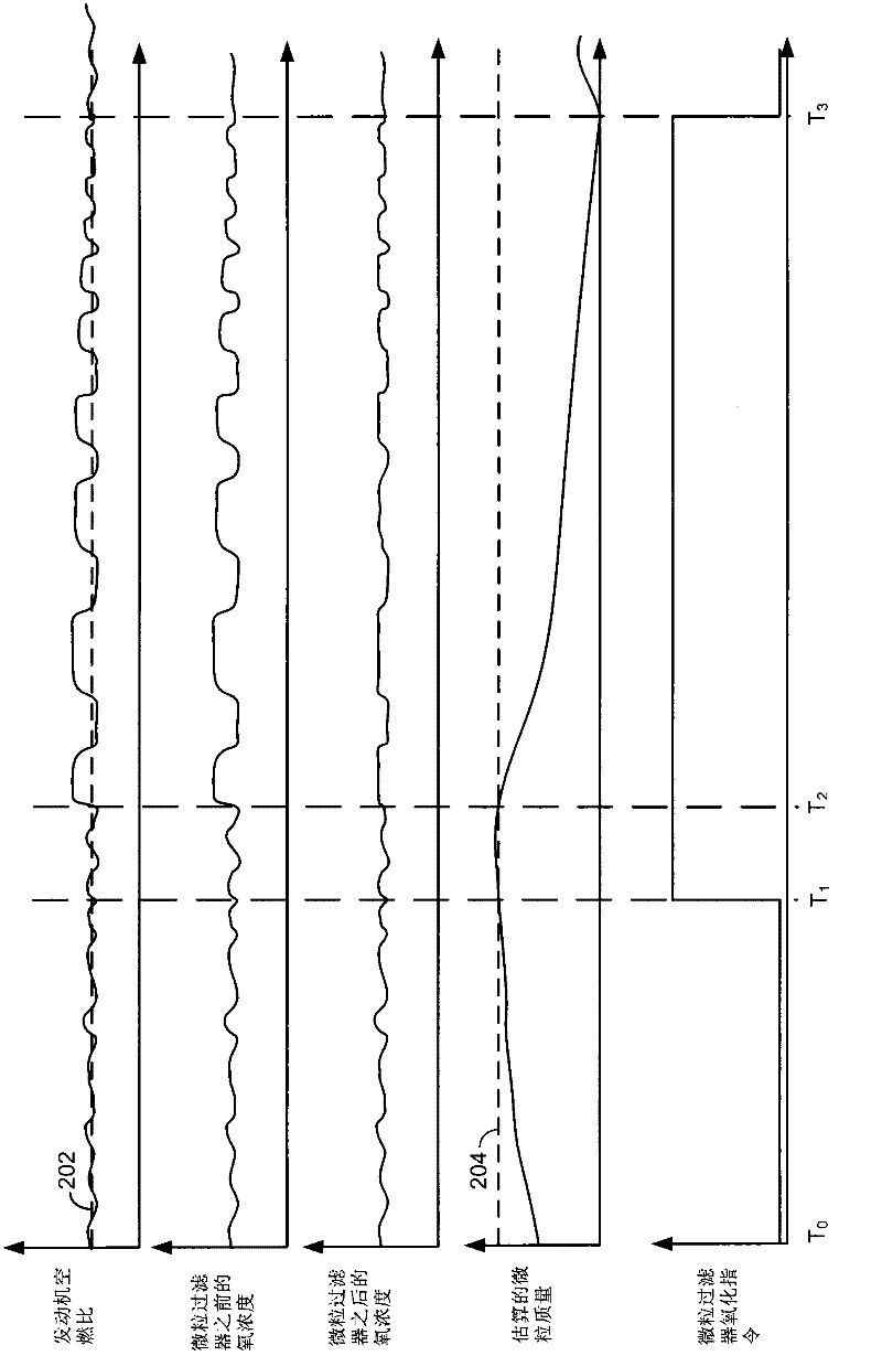
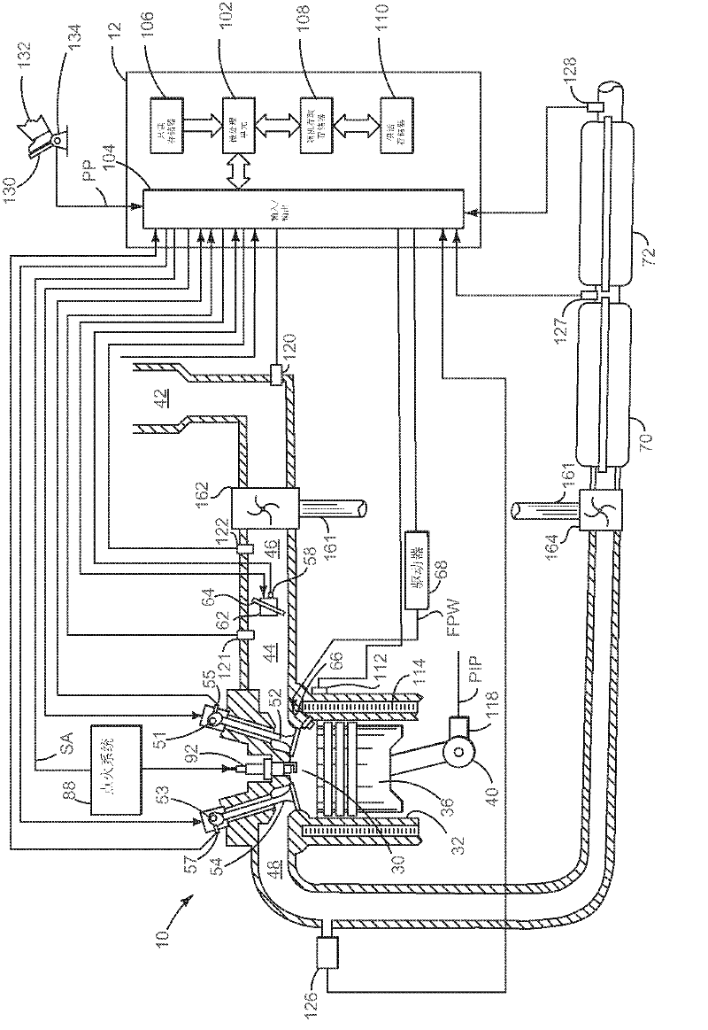
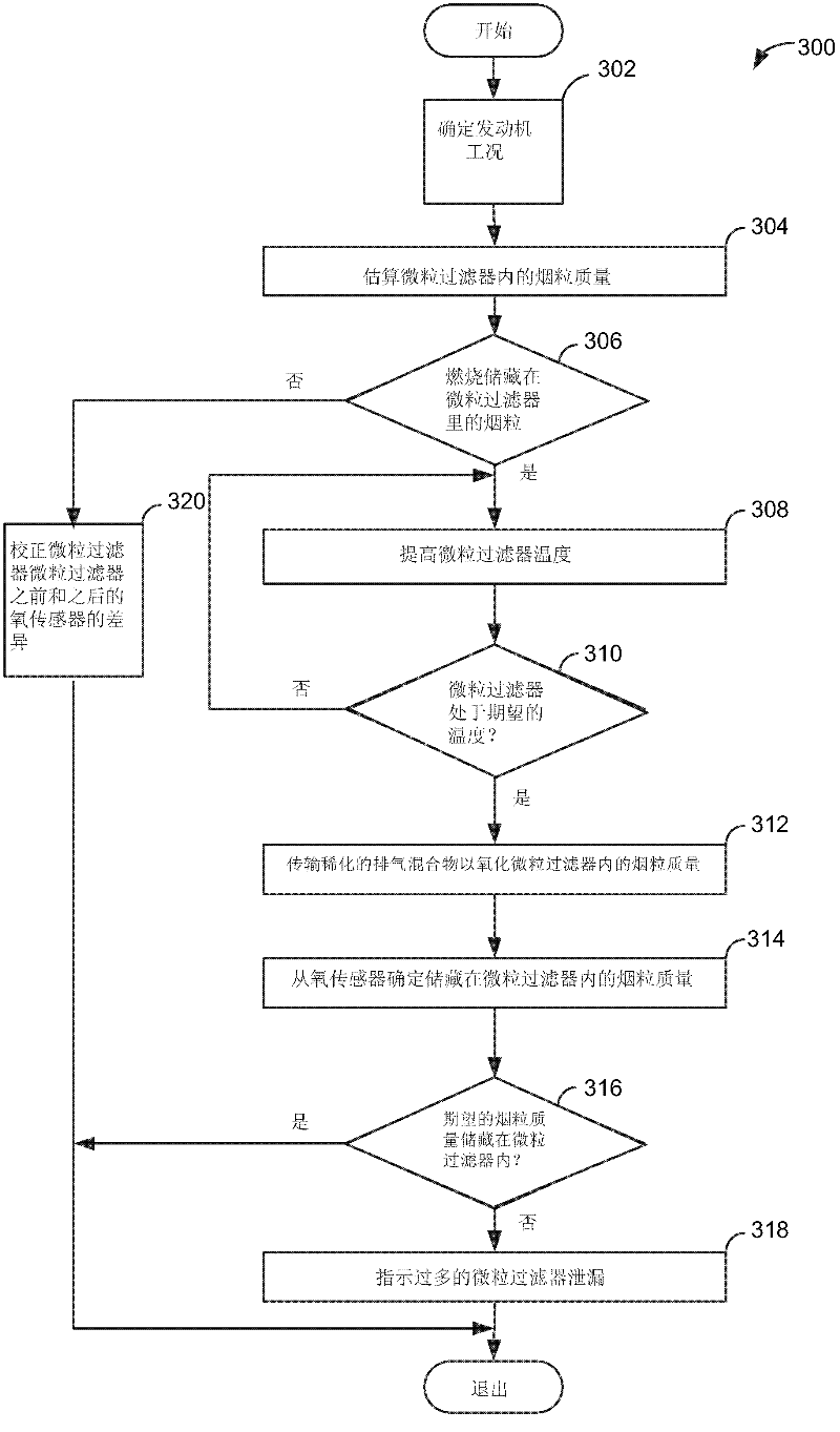
[0024] This description is directed to the determination of the mass of oxidized soot within a particulate filter. figure 1 One embodiment of a system including a particulate filter is shown. The system includes a spark ignition engine that can run on gasoline, alcohol, or a mixture of gasoline and alcohol. figure 2 The expected correlation signal for a system estimating soot mass from an oxygen sensor is shown. available by figure 1 system execution in Figure 3-5 The method in implements the signal.

[0025] refer to figure 1 , including multiple cylinders ( figure 1 An internal combustion engine 10 of which one cylinder is shown in ) is controlled by an electronic engine controller 12 . Engine 10 includes combustion chamber 30 and cylinder walls 32 with piston 36 positioned therein and connected to crankshaft 40 . Combustion chamber 30 is shown communicating with intake manifold 44 , exhaust manifold 48 via respective intake valve 52 , exhaust valve 54 . Each intak...


PUM


Abstract

A method for determining soot mass oxidized during a particulate filter oxidation procedure is disclosed. In one example, soot mass is determined via an Arrhenius equation. The approach may provide cost savings and reliability improvements as compared to other ways of determining soot mass.

Description

【Technical field】 [0001] The invention relates to a method for determining the mass of soot stored in a particulate filter. 【Background technique】 [0002] Carbonaceous soot may be a secondary product of some combustion processes. For example, some diesel engines may produce carbonaceous soot during periods of high engine load. More recently, gasoline engines have incorporated direct fuel injection into the engine cylinders to improve engine performance and fuel economy. However, injecting fuel directly into the engine cylinders also increases the likelihood of gasoline engines producing carbonaceous soot. Therefore, some manufacturers consider installing particulate filters in the exhaust system of gasoline engines. [0003] The particulate filter retains carbonaceous soot, but over time, the accumulated soot in the particulate filter can reduce the flow of exhaust gas through the exhaust system. Therefore, engine back pressure may increase, thereby reducing engine effi...

Claims


Application Information

Patent Timeline
IPC IPC(8): F01N3/035F01N11/00
CPCF01N3/101F01N11/007F01N13/009F01N2550/04F01N2560/025F01N2560/14F01N2900/1606F01N2900/1624F02D41/029F02D41/1441F02D2200/0812F02D2200/0814Y02T10/12Y02T10/40
Inventor M·J·范尼马斯塔特
Owner FORD GLOBAL TECH LLC
Why Eureka
Try Eureka