Pressure relief and diversion structure of water storage bottle for automobile

A technology for water storage bottles and automobiles, applied in engine components, machines/engines, engine cooling, etc., can solve the problems of lack of protective measures, pollution, unstable pressure control, etc., to reduce manufacturing difficulty, manufacturing cost, pressure Controlling stable effects

Active Publication Date: 2016-03-02
CHONGQING CHANGAN AUTOMOBILE CO LTD
View PDF5 Cites 2 Cited by
  • Summary
  • Abstract
  • Description
  • Claims
  • Application Information

AI Technical Summary

Problems solved by technology

The pressure relief device commonly used now is to install a pressure relief cover on the water storage bottle, but there is no diversion structure on the water storage bottle, which will lead to the following shortcomings: 1) When the cooling system is under high pressure, through the storage After the vapor-liquid mixture discharged from the exhaust port of the water bottle is pushed out of the valve, it splashes to the outside of the bottle and causes pollution; 2) When the cap of the water storage bottle is to be opened due to illegal operation or other reasons, there are no necessary protective measures, and it is subjected to high-pressure cooling The coolant in the system will be sprayed directly upwards, causing personal injury
[0003] In addition, the vacuum valve and the pressure-relief valve are arranged side by side in the bottle cap of the existing water bottle for automobiles, which has the following disadvantages: 1) The exhaust valve and the intake valve are set up separately. Influenced by the relatively small volume of the valve body, the control accuracy of the valve body is too high, and the pressure control is unstable, so that the valve cannot accurately and timely control the pressure in the bottle; 2) Due to the small volume of the valve body, the inside of the bottle cap The structure is complex and the processing is difficult; 3) Due to the small size of the valve body, when there is a vacuum or excessive pressure inside the system, the internal pressure of the system cannot be balanced through the valve body in time, making the whole vehicle in an "uncomfortable" state for a long time. Will shorten the "life" of the vehicle

Method used


Image

  • Pressure relief and diversion structure of water storage bottle for automobile
  • Pressure relief and diversion structure of water storage bottle for automobile
  • Pressure relief and diversion structure of water storage bottle for automobile

Examples


Embodiment Construction

[0018] Below in conjunction with accompanying drawing, the present invention will be further described:

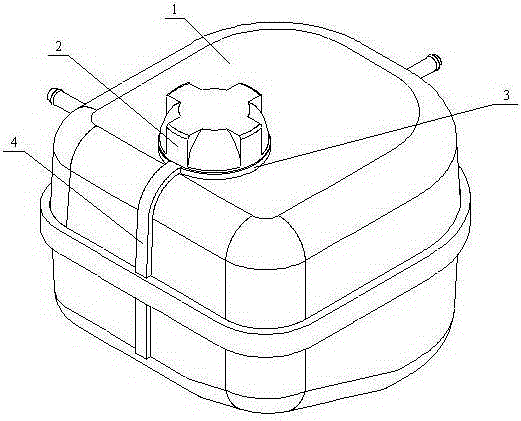
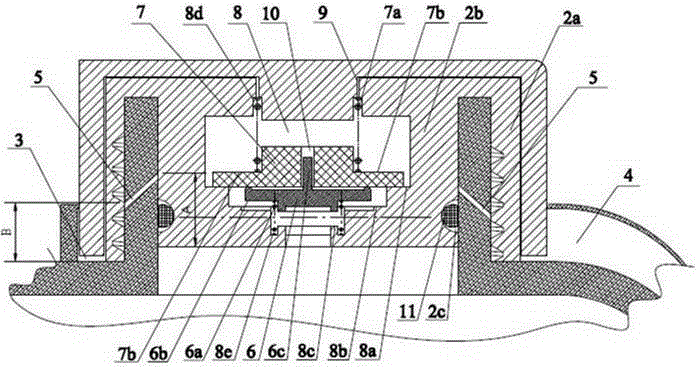
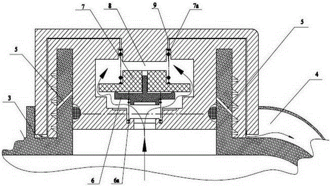
[0019] Such as figure 1 , figure 2 As shown, a pressure relief and diversion structure for a water storage bottle for automobiles includes a bottle body 1 and a bottle cap 2, and also includes an annular groove 3 surrounding the lower end of the neck of the bottle body 1, which serves to gather high-temperature and high-pressure steam. effect of the liquid mixture. The bottle cap 2 is divided into an outer cap 2a and a cap plug 2b. There is a bottle cap inner cavity 8 at the center of the cap plug 2b, in which an intake and exhaust valve is installed to control the intake and exhaust of the engine cooling system respectively. An active venting channel 9 is provided inside the outer cover 2 , one end of which is connected to the inner cavity 8 of the bottle cap, and the other end extends into the annular groove 3 ; a manual venting hole 5 is provided in the middle of the...


PUM


Abstract

The invention provides a decompression and stream guidance structure of an automobile water storage bottle. The decompression and stream guidance structure comprises a bottle body and a bottle cover, and is characterized by further comprising an annular groove around the lower end of a neck of a bottle body. The bottle cover is divided into an outer cover and a cover plug; a bottle cover inner cavity is arranged at the center of the cover plug, and an air inlet-outlet valve is mounted in the bottle cover inner cavity; a driving air leakage channel is arranged inside the outer cover; one end of the driving air leakage channel is connected with the bottle cover inner cavity, and the other end of the driving air leakage channel extends into the annular groove; and a manual air leakage hole is formed in the middle section of the neck of the bottle body. According to the decompression and stream guidance structure provided by the invention, on the one hand, the design of the annular groove and a stream guidance groove is used, so that a high-pressure gas-liquid mixture does not splash outside the bottle to cause pollution; and on the other hand, the manual decompression hole is arranged, so that a high-pressure cooling liquid in the bottle is rapidly decompressed when the water storage bottle is opened, and the personal injury is avoided.

Description

technical field [0001] The invention belongs to the field of automobile engine cooling systems, and in particular relates to a pressure relief and diversion structure for an automobile water storage bottle. Background technique [0002] During the working process of the engine, the temperature of the coolant in the cooling system will increase, which will cause it to expand. Even when the engine power suddenly increases, the coolant flowing through the cylinder liner will be vaporized in large quantities, and the steam generated will make the The cooling system, especially the radiator, is under relatively high pressure. At this time, a pressure relief device is required to relieve the pressure of the radiator. The pressure relief device commonly used now is to install a pressure relief cover on the water storage bottle, but there is no diversion structure on the water storage bottle, which will lead to the following shortcomings: 1) When the cooling system is under high pre...

Claims


Application Information

Patent Timeline
Patent Type & Authority Patents(China)
IPC IPC(8): F01P11/00F01P11/02
Inventor 辜积峰蔡操平孟锐郑军于海燕
Owner CHONGQING CHANGAN AUTOMOBILE CO LTD
Why Eureka
Try Eureka