Self-control kite group generator

A technology for generators and kite sets, which is applied to wind turbine components, wind power generation, wind engines, etc., can solve the problems of complex structure, weight increase, length error accumulation, etc., and achieve large transmission ratio range, low manufacturing cost, and utilization rate-enhancing effect

Inactive Publication Date: 2012-09-05
周振文
View PDF5 Cites 6 Cited by
  • Summary
  • Abstract
  • Description
  • Claims
  • Application Information

AI Technical Summary

Problems solved by technology

[0002] At present, the known merry-go-round kite generator consists of a large turntable, a kite, a cable, a speed-increasing transmission device, a generator, a power transmission system, and a control system, and has the following disadvantages: the large turntable is too large, and the kite attitude control device is accompanied by The kites fly into the air together, and the weight increases. The energy required for kite attitude control requires a separate power generation device. The kite attitude control requires a complex wireless remote control device with a complex structure.
U.S. Patent U.S.6072245 discloses that the high-strength ropes on both sides of the device for utilizing wind energy inevitably have length errors. This device utilizing wind energy runs continuously, and length errors accumulate continuously, causing the kite to gradually lose its balance.

Method used


Image

  • Self-control kite group generator
  • Self-control kite group generator
  • Self-control kite group generator

Examples


Embodiment Construction

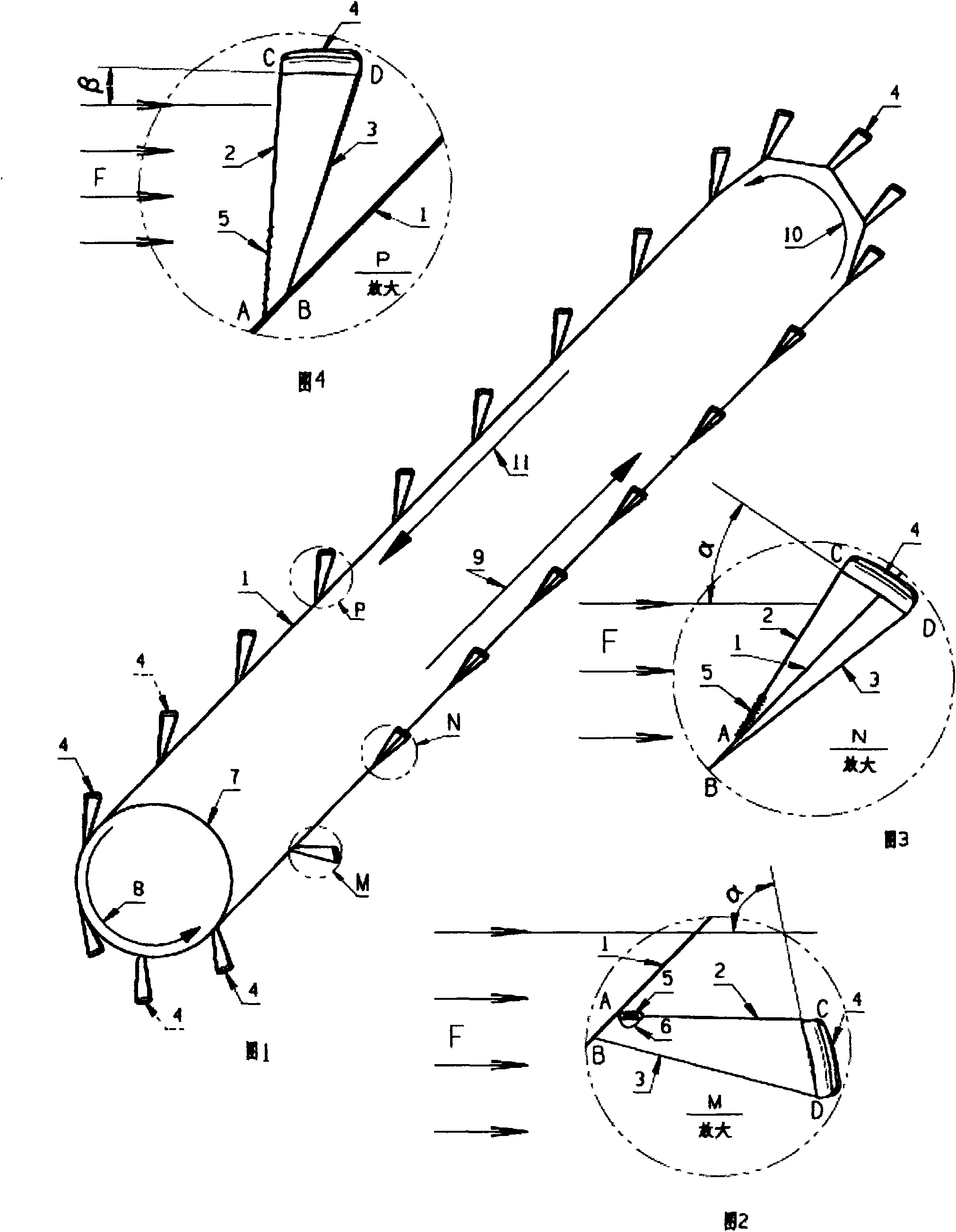
[0038] The cableway (1) is made of ultra-high-strength polyethylene fiber, the total length of the rope is 6,000 meters, and the diameter of the rope (1) is 30 mm. The length of the circular cableway (1) formed is 3,000 meters, and the flying height of the kite can reach 2,000 meters. The power is 1MW, the design speed of the cableway is 4 m / s, the distance between the kites in the length direction of the cableway (1) is 10 meters, the number of kites is 300, and the area of ​​each kite is 10 square meters. One end of the upper stay wire (2) is connected to the cableway Point A of (1), the other end is connected to the upper end of the kite body (4), and one end of the pull-down line (3) is concentratedly connected to the B point of the cableway (1), and the other end is connected to the lower end of the kite body (4), C Point is the end point on the center line of kite body (4), D point is the end point below the center line of kite body (4), and the distance between A and B i...


PUM


Abstract

The invention relates to a device for utilizing wind energy, which is characterized by comprising at least ten kites capable of automatically controlling windward angles, a circularly-operated cableway combination and a multi-rope and multi-roller transmission device, wherein one end of a pulling-up wire (2) is intensively connected with a point A of a cableway (1) and the other end of the pulling-up wire is connected with the upper end of each kite body (4); one end of a pulling-down wire (3) is intensively connected with a point B of the cableway (1) and the other end of the pulling-down wire is connected with the lower end of each kite body (4); a point C is an upper end point of a central line of each kite body (4) and a point D is a lower end point of the central line of each kite body (4); a hinged four-rod mechanism is formed by an AB connecting line, an AC connecting line, a CD connecting line and a BD connecting line; according to a movement principle of the hinged four-rod mechanism, a windward angle alpha of the kite (N) at an acting state is greater than a windward angle beta of the kite (P) at a returning state; wind acting force of the kite (N) at the acting state is more than wind acting force of the kite (P) at the returning state; the cableway (1) drives a large transmission wheel (7), a transmission shaft (13), a multi-rope transmission device and a generator (19) to generate power along a direction indicated by an arrow (9).

Description

technical field [0001] The invention relates to a device for utilizing wind energy, in particular to a device for generating electricity using kites. Background technique [0002] At present, the known merry-go-round kite generator consists of a large turntable, a kite, a cable, a speed-increasing transmission device, a generator, a power transmission system, and a control system, and has the following disadvantages: the large turntable is too large, and the kite attitude control device is accompanied by The kites fly into the air together, and the weight increases. The energy required for the kite attitude control requires a separate power generation device. The kite attitude control requires a complex wireless remote control device with a complex structure. [0003] US patent U.S. 6072245 discloses a device for harnessing wind energy comprising a plurality of kites connected to high strength ropes forming a loop. The kite alternates from an ascending route to a descending...

Claims


Application Information

Patent Timeline
Patent Type & Authority Applications(China)
IPC IPC(8): F03D9/00F03D5/02F03D7/00F03D11/04F03D9/25F03D13/20
CPCY02E10/70Y02E10/72
Inventor 周振文周宁
Owner 周振文
Why Eureka
Try Eureka