Photo ionization detector

A photoionization and detector technology, applied in the field of gas chromatography analysis instruments, can solve problems such as the decrease of detector sensitivity

Inactive Publication Date: 2012-09-12
DALIAN INST OF CHEM PHYSICS CHINESE ACAD OF SCI
View PDF3 Cites 11 Cited by
  • Summary
  • Abstract
  • Description
  • Claims
  • Application Information

AI Technical Summary

Problems solved by technology

The electrode emits electrons under the irradiation of vacuum ultraviolet light, forming a back

Method used


Image

  • Photo ionization detector
  • Photo ionization detector
  • Photo ionization detector

Examples


Embodiment Construction

[0020] The present invention will be further described below in conjunction with the accompanying drawings.

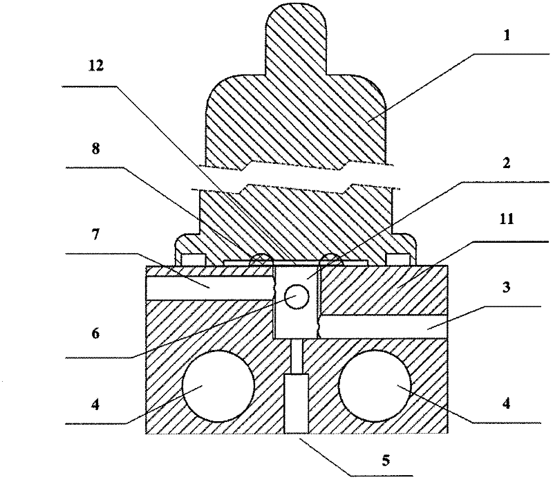
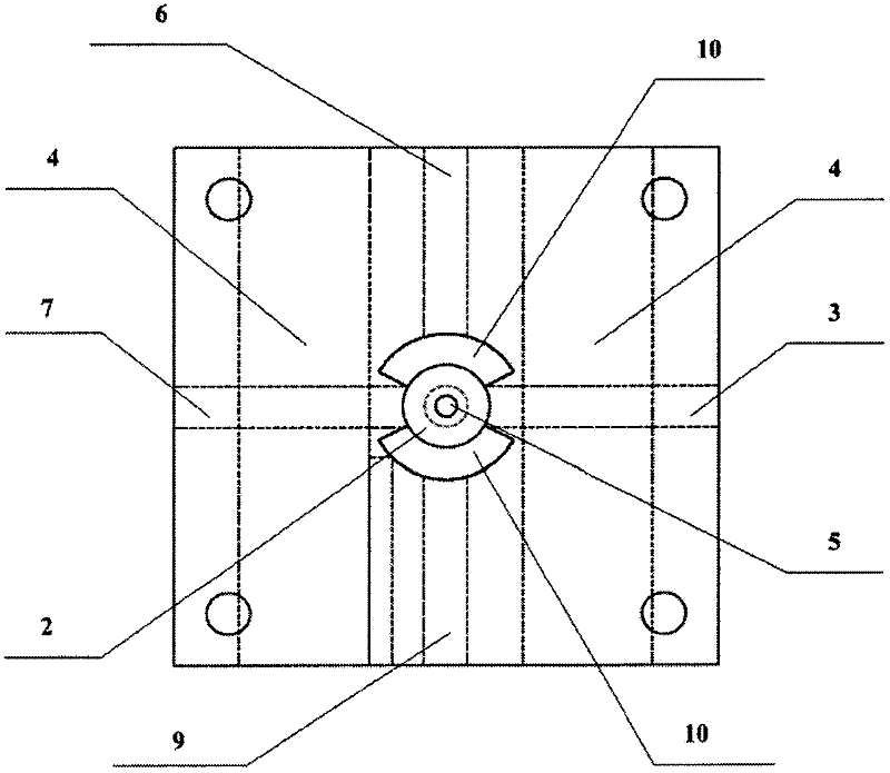
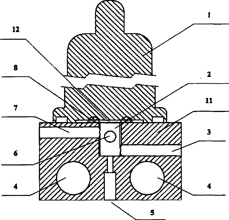
[0021] Such as figure 1 with 2 As shown, a photoionization detector includes a vacuum ultraviolet lamp 1 and an ionization chamber 2 . The optical path of the vacuum ultraviolet lamp 1 is parallel to the axis of the electrodes. The ionization chamber 2 includes two symmetrically arranged electrodes with a radial cross section of a minor arc, one is a polarizing electrode 6 and the other is a collecting electrode 9 .

[0022] The ionization chamber pool body 11 is made of polytetrafluoroethylene material, one side of which directly contacts with the vacuum ultraviolet light window 12 and is sealed by a polytetrafluoroethylene sealing ring 8 .

[0023] Both ends of the arc surfaces of the two electrodes are respectively connected through insulating materials to form a ring-shaped electrode. The ring electrode is embedded in the polytetrafluoroethylene cell body 11 to...


PUM

PropertyMeasurementUnit
Lengthaaaaaaaaaa
Widthaaaaaaaaaa
Heightaaaaaaaaaa

Abstract

The invention discloses a photo ionization detector, comprising a vacuum ultraviolet lamp and an ionization chamber, wherein the ionization chamber comprises two electrodes with minor arc radial cross sections, wherein the electrodes are arranged symmetrically, and comprise a polarized electrode and a collecting electrode. The two electrodes insert into the interior of polytetrafluoroethylene tank in the ionization chamber, such that base current and noise of the electrodes caused by irradiation of the vacuum ultraviolet lamp are avoided. The detector contains an automatically cleaning system to prevent decreasing of sensitivity of the detector caused by pollution of light window and electrodes when the detector is in a continuous operation for a long time. The photo ionization detector suits as a detector of a portable gas chromatograph and a rapid gas chromatograph.

Description

technical field [0001] The invention relates to a gas chromatography analysis instrument, in particular to a photoionization detector. Background technique [0002] The photoionization detector (PID) uses vacuum ultraviolet radiation to ionize the measured components to generate signals, which can be used alone as a chromatographic detector or used in series with flame ionization detectors, mass spectrometers and other detectors. [0003] The working principle of the photoionization detector is: the effluent of the chromatographic column is brought into the ionization chamber by the carrier gas, the gas to be measured is ionized under the irradiation of vacuum ultraviolet light, and the generated electrons and positive ions are respectively charged to the ionization chamber under the electric field of the polarized plate. The migration of the two poles causes changes in the induced charge of the collecting electrode plate, and the weak current passes through the amplifier to...

Claims


Application Information

Patent Timeline
IPC IPC(8): G01N30/64
Inventor 李海洋吴婧崔华鹏梁茜茜王祯鑫赵琨
Owner DALIAN INST OF CHEM PHYSICS CHINESE ACAD OF SCI
Why Eureka
Try Eureka