Laser radar device for measuring mine gas concentration distribution and working method thereof

A laser radar and gas concentration technology, which is applied in measuring devices, radio wave measurement systems, color/spectral characteristic measurement, etc., can solve the inconvenience of underground gas concentration, cannot accurately reflect gas concentration, and the sensor does not have the function of distance measurement and other problems, to achieve the effect of compact structure, high ranging accuracy and cost reduction

Active Publication Date: 2012-09-12
山东华辰泰尔信息科技股份有限公司
View PDF4 Cites 35 Cited by
  • Summary
  • Abstract
  • Description
  • Claims
  • Application Information

AI Technical Summary

Problems solved by technology

However, the above-mentioned sensors do not have the function of distance measurement, so they cannot accurately reflect the concentration of gas in each area of ​​the mine, which brings a lot of inconvenience to judging whether the gas concentration in the mine is safe.

Method used


Image

  • Laser radar device for measuring mine gas concentration distribution and working method thereof
  • Laser radar device for measuring mine gas concentration distribution and working method thereof
  • Laser radar device for measuring mine gas concentration distribution and working method thereof

Examples


Embodiment 1

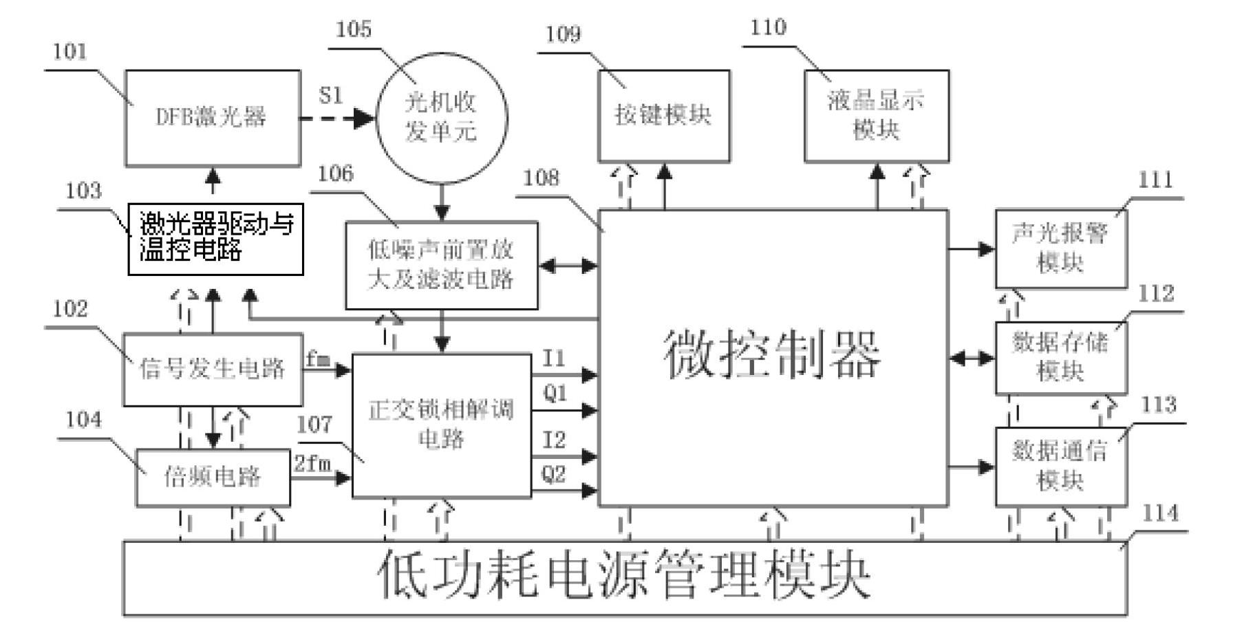
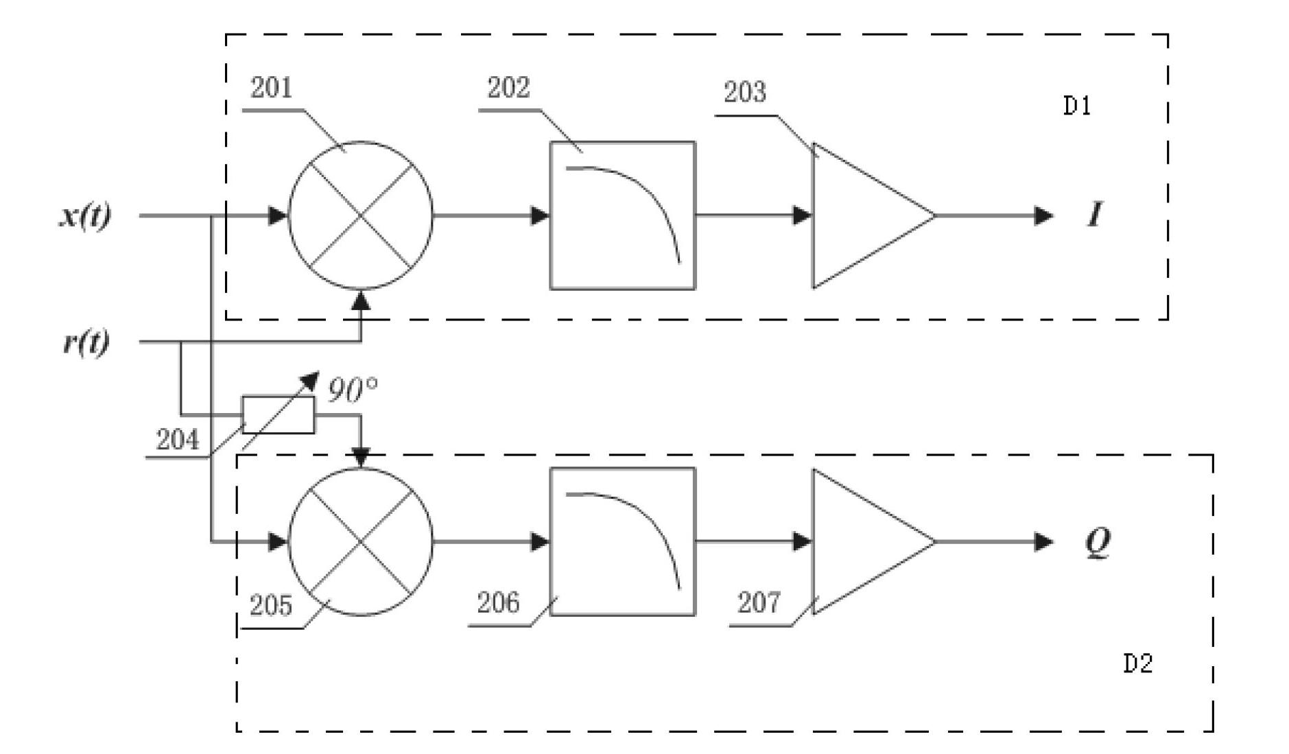
[0038] Such as figure 1 , 2 as shown,

[0039] A laser radar device for measuring the concentration distribution of mine gas, which includes a DFB laser 101, a signal generating circuit 102, a laser drive and temperature control circuit 103, a frequency multiplication circuit 104, an optical transceiver unit 105, a low-noise preamplifier and a filter circuit 106. Quadrature phase-locked demodulation circuit 107, microcontroller 108, key module 109, liquid crystal display module 110, sound and light alarm module 111, data storage module 112, data communication module 113 and low power consumption power management module 114;

[0040] The central wavelength of the DFB laser 101 is 1653.7nm; the DFB laser 101 emits a narrow-linewidth infrared laser with a wavelength of 1653.7nm, and the central wavelength corresponds to methane gas with a strong infrared absorption peak, which can treat methane Accurate gas detection; the DFB laser 101 can also emit wavelength-scanned laser lig...

Embodiment 2

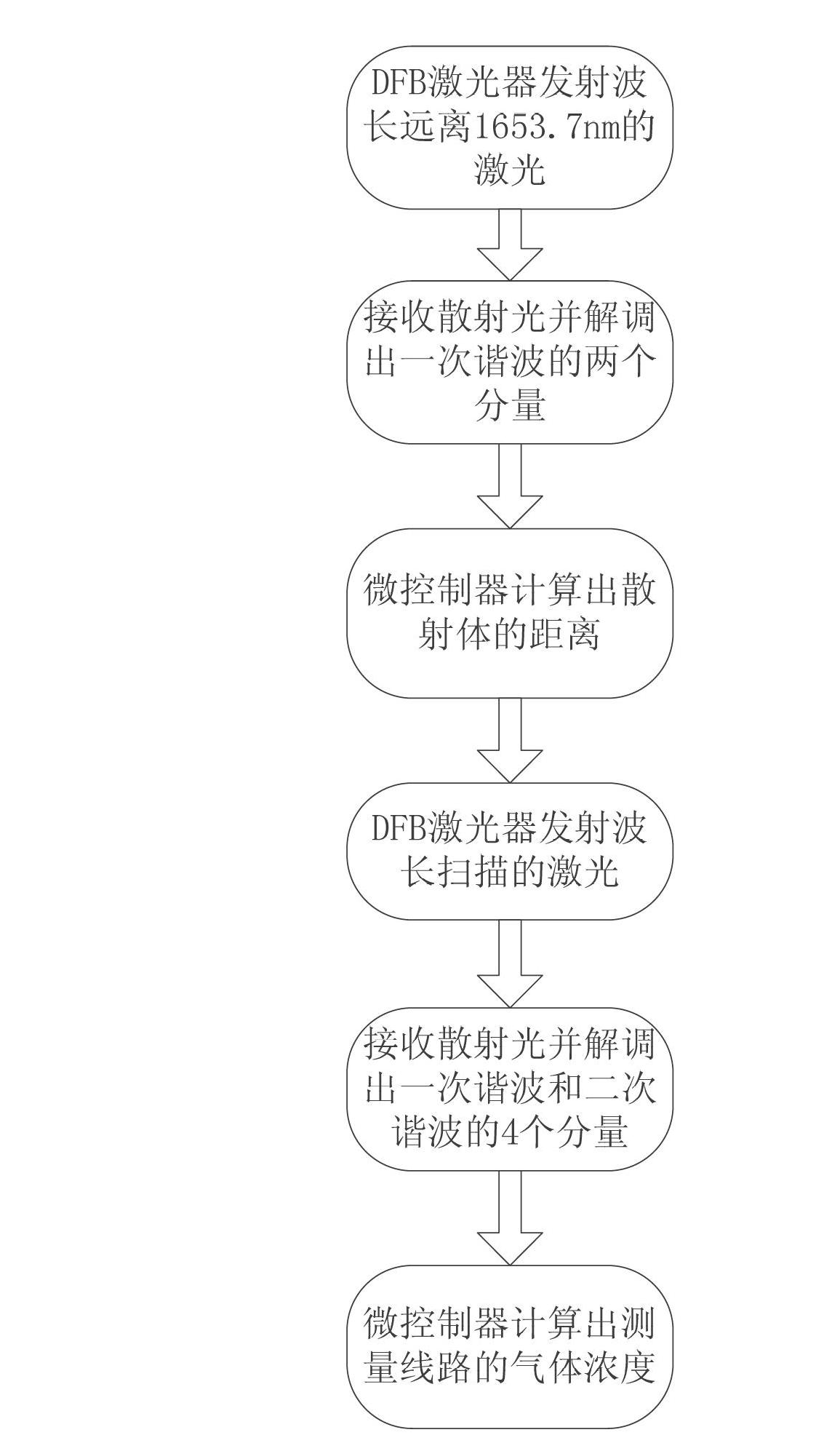
[0051] A kind of working method of the lidar device of measuring mine gas concentration distribution as described in embodiment 1, such as image 3 shown, including the following steps:

[0052] (1) The microcontroller 108 controls the laser drive and temperature control circuit 103 to make the DFB laser 101 emit laser light with a wavelength that deviates from 1653.7nm, and the laser light with a wavelength that deviates from 1653.7nm is a laser with a wavelength of 1653.6nm, and the 1653.6nm laser enters the optical machine for transceiver Unit 105, emitting through the fiber collimator;

[0053] (2) The 1653.6nm laser emitted by the fiber collimator in step (1) will not be absorbed by the gas, but will be finally reflected by the background terrain scattering body to form scattered light, and the scattered light will be focused onto the photodetector , converted into a current signal; the current signal is sent to the quadrature phase-locked demodulation circuit 107 for de...


PUM

PropertyMeasurementUnit
wavelengthaaaaaaaaaa

Abstract

The invention relates to a laser radar device for measuring mine gas concentration distribution, comprising a DFB (Distributed Feed Back) laser (101), a signal generating circuit (102), a laser driving and temperature control circuit (103), a frequency doubling circuit (104), an optical machine transmitting / receiving unit (105), a low-noise preamplifier and filter circuit (106), an orthogonal phase locking demodulation circuit (107), a micro-controller (108), a key module (109), a liquid crystal display module (110), an audible and visual alarm module (111), a data storage module (112), a data communication module (113) and a low-power consumption power management module (114). The laser radar device for measuring mine gas concentration distribution provided in the invention is also capable of measuring the distance between a gas leakage point and a measurement point while measuring the gas concentration, and further capable of finding out the source of gas outburst in a mine conveniently and quickly.

Description

technical field [0001] The invention relates to a laser radar device for measuring mine gas concentration distribution and a working method thereof, belonging to the technical field of detection of underground gas concentration. Background technique [0002] Gas explosion accidents cause heavy casualties to people's lives every year. When the concentration of gas in coal mines is within the explosion limit of 5%-15% and is not dealt with, it will pose a serious threat to the safety of coal miners. , so it is of great significance to develop a measuring device for mine gas concentration. At the same time, if the distribution of the gas concentration can be measured at the same time as the concentration of the gas, the distribution of the concentration of the gas in a certain area can be known more clearly, which is more meaningful for the investigation of danger. [0003] Tuned Laser Absorption Spectroscopy (TDLAS) is used for gas concentration detection. It has the advantag...

Claims


Application Information

Patent Timeline
Patent Type & Authority Applications(China)
IPC IPC(8): G01S17/06G01N21/35G01N21/3504
Inventor 孙延光龚尚庆董作人叶青蔡海文侯绍森张佳杰
Owner 山东华辰泰尔信息科技股份有限公司
Why Eureka
Try Eureka