
Induction type wireless energy transmission light emitting diode (LED) drive circuit

A wireless energy transmission, LED driving technology, applied in circuit devices, electric lamp circuit layout, electric light source and other directions, can solve the problem of the heat interaction between the driving circuit and the LED light source, to reduce the stress and loss of the device, high reliability, Avoid interactive effects

Inactive Publication Date: 2012-09-12
SOUTHEAST UNIV
View PDF5 Cites 14 Cited by
  • Summary
  • Abstract
  • Description
  • Claims
  • Application Information

AI Technical Summary

Problems solved by technology

[0004] The object of the present invention is to provide an LED drive circuit for inductive wireless energy transmission. The drive circuit solves the problem of the mutual influence of the drive circuit and the heat of the LED light source, improves the stability of the LED lighting system, and greatly increases the power of the LED. Lifespan and Luminous Efficiency

Method used


Image

  • Induction type wireless energy transmission light emitting diode (LED) drive circuit
  • Induction type wireless energy transmission light emitting diode (LED) drive circuit
  • Induction type wireless energy transmission light emitting diode (LED) drive circuit

Examples


Embodiment Construction

[0018] Specific embodiments of the present invention will be further described below in conjunction with the accompanying drawings.

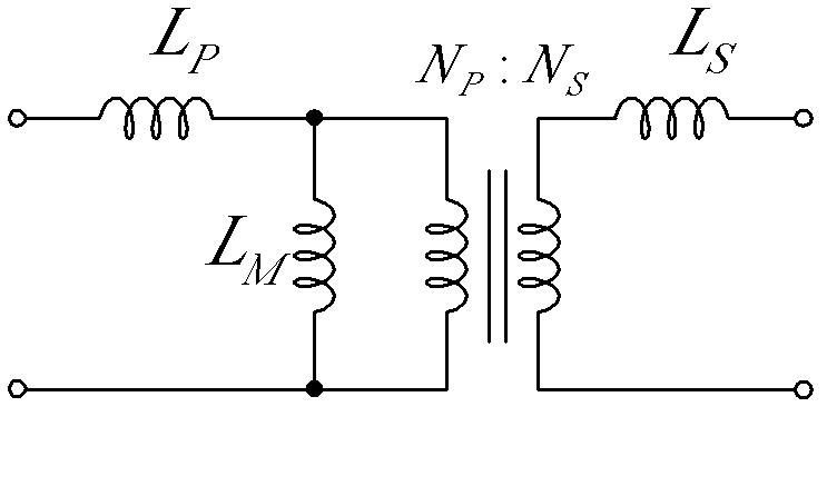
[0019] Such as figure 2 As shown, an LED drive circuit for inductive wireless energy transmission includes a power factor correction circuit 1, an inverter circuit 3, a loosely coupled transformer T, and a primary side resonant capacitor C P , Secondary side resonant capacitor C s and a rectifier circuit 8; the input end of the power factor correction circuit 1 is connected to an AC power supply; the DC output end of the power factor correction circuit 1 is connected to the DC input end of the inverter circuit 3; the AC output end of the inverter circuit 3 is connected to the original loose coupling transformer T side of the two input terminals, where the primary side resonant capacitor C P Connect between any end of the primary side of the loosely coupled transformer T and the output of the inverter circuit 3; the two output terminals of the...


PUM


Abstract

The invention discloses an induction type wireless energy transmission light emitting diode (LED) drive circuit, which comprises a power factor correction circuit, an inverter circuit, a loosely coupled transformer, a rectifier circuit and an LED light source; wherein the output end of the power factor correction circuit is connected with the input end of the inverter circuit, the output end of the inverter circuit is connected with the primary side of the loosely coupled transformer, the secondary side of the loosely coupled transformer is connected with the alternating current input end of the rectifier circuit, the direct current output end of the rectifier circuit is connected with the power supply terminal of the LED light source. Compared with the prior art, the drive circuit disclosed by the invention has the advantages that wireless energy transmission LED drive circuit is realized by using a loosely coupled transformer; the interaction of the heat dissipation of the drive circuit and the heat dissipation of the LED light source is avoided; the voltage of the switching device and the current stress are decreased by a resonant circuit; the luminous efficiency, the quality of light, and the service life of the LED light source are improved by the drive circuit; the high efficiency and high reliability of the LED driver is guaranteed.

Description

technical field [0001] The invention relates to an LED driving circuit. Background technique [0002] LED drivers are high-frequency electronic products with high power density and high integration. The various electronic components used will generate losses during operation, such as the conduction loss and switching loss of switching devices and the high-frequency operation of magnetic components. Iron loss and copper loss, etc., these losses are dissipated in the form of heat energy. [0003] The LED lighting fixtures currently produced often integrate the light source and the driver to achieve plug and play. In the LED lamps with airtight packaging and small space, there is no effective heat dissipation conditions such as radiation and convection. The thermal effects of the LED light source and the driver affect each other. It causes LED aging to be accelerated, its efficiency becomes lower, its life is shortened, and its light color drifts. In addition, as the ambient ...

Claims


Application Information

Patent Timeline
Patent Type & Authority Applications(China)
IPC IPC(8): H05B37/02H02J17/00H02J50/10
Inventor 曲小慧黄少聪黄学良谢智刚
Owner SOUTHEAST UNIV
Learn More