Module design for the components of a tank for storing a reducing agent

A reducing agent and bearing plate technology, which is applied to vehicle parts, mechanical equipment, engine components, etc., can solve the problems of increased risk of damage, etc., to increase the usable tank volume, improve the ice compressive strength, and improve the degree of freedom of innovation Effect

Active Publication Date: 2012-09-12
ROBERT BOSCH GMBH
View PDF7 Cites 7 Cited by
  • Summary
  • Abstract
  • Description
  • Claims
  • Application Information

AI Technical Summary

Problems solved by technology

Increased risk of d

Method used


Image

  • Module design for the components of a tank for storing a reducing agent
  • Module design for the components of a tank for storing a reducing agent
  • Module design for the components of a tank for storing a reducing agent

Examples


Embodiment Construction

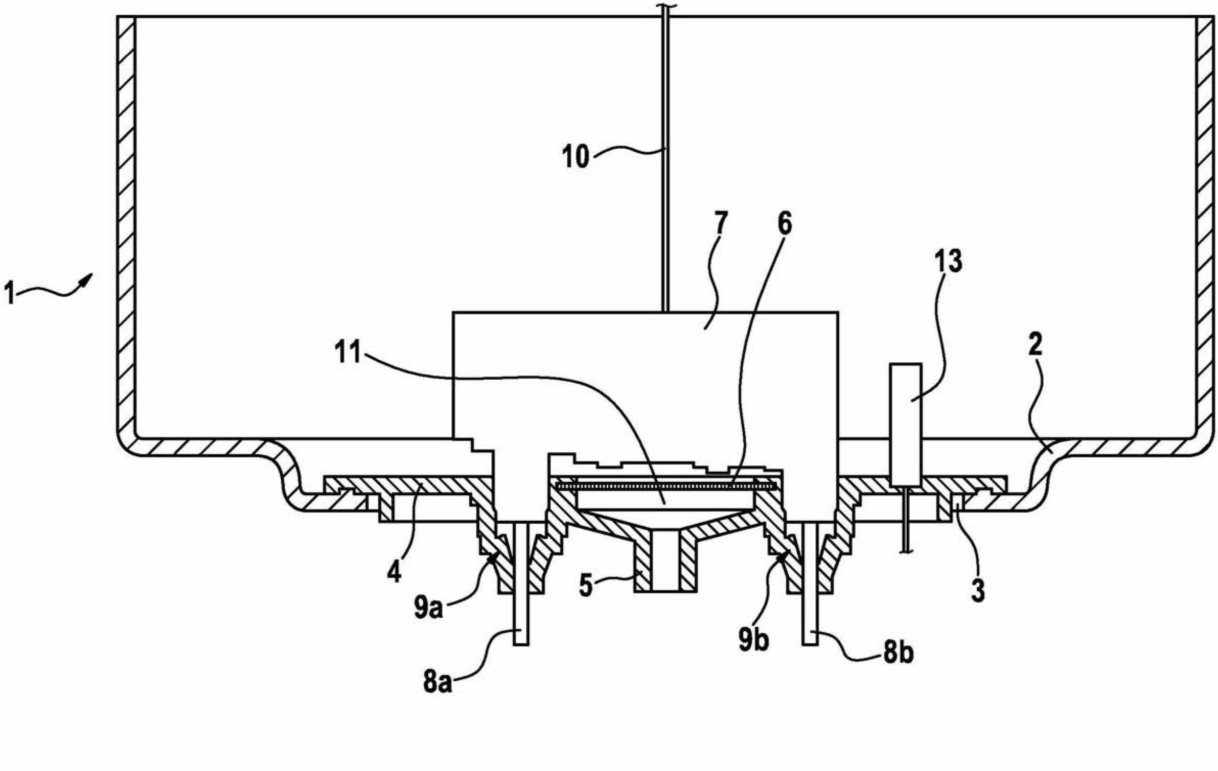
[0022] exist figure 1 The tank 1 shown in cross-section in FIG. 1 stores a reducing agent that reduces nitrogen oxides produced in the exhaust gas of an internal combustion engine into nitrogen and water. As a result, the reducing agent delivered from the tank via a supply module (not shown) is injected into the exhaust gas line of the internal combustion engine.

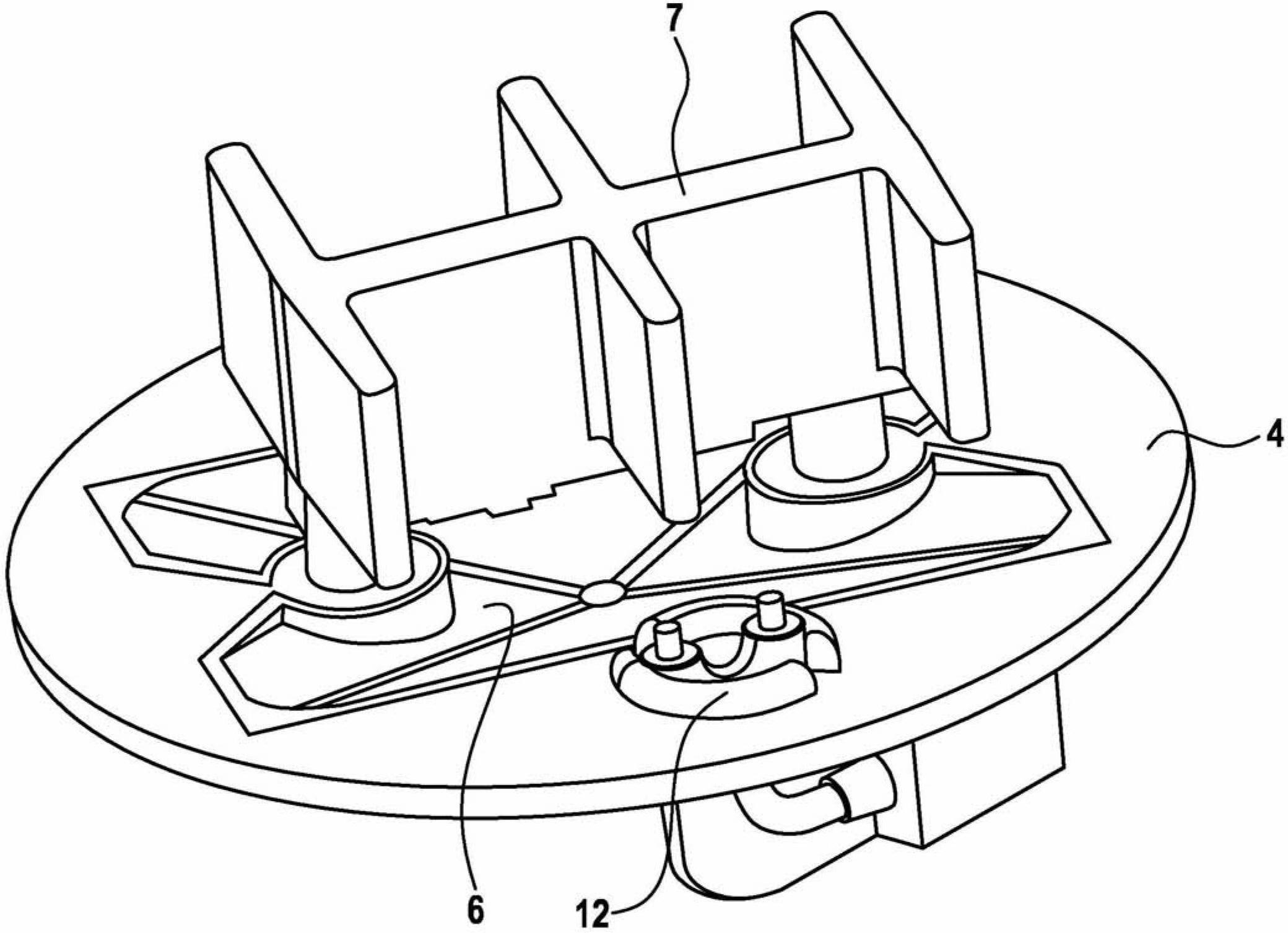
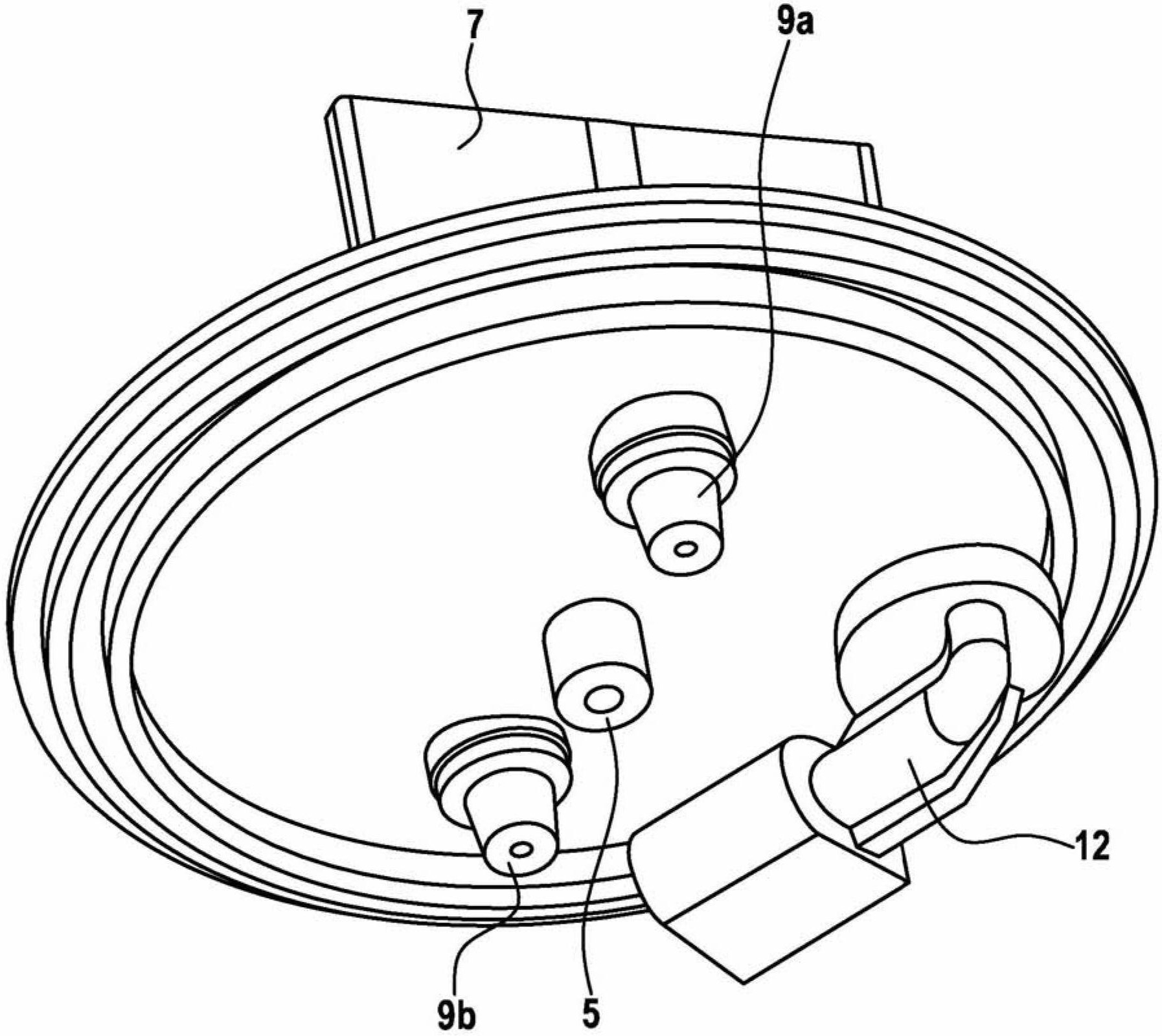
[0023] In the bottom area 2 , the tank 1 has an arbitrary geometric shape, in particular an annular opening 3 , which is closed tightly with a carrier plate 4 . Thus, the carrier plate 4 may comprise a seal, eg screwed, to the tank 1 . The carrier plate 4 has line ports 5 for line connections and / or return lines, wherein, if the line ports 5 are connected to a draw line, the line ports 5 are connected to a filter 6 in the form of a filtering screen. According to an embodiment, the line connection 5 is preferably configured as a single port for the suction line. However, the line port 5 can also be configured as a...


PUM


Abstract

The invention relates to a tank (1) for storing a reducing agent, in particular a liquid reducing agent, by means of which nitrogen oxide can be reduced out of the exhaust gas of an internal combustion engine into nitrogen and water, wherein the tank (1) has a floor region (2) and a head region and furthermore a line connection (5) is utilized in the tank (1) for a suction line and/or a return line and a heater (7, 7a). The tank (1) for storing a reducing agent according to the invention is improved over the prior art and does not have the disadvantages thereof. Said improvement is achieved in that the line connection (5) for the suction line and/or the return line and the heater (7, 7a) are integrated in a carrier plate (4) and the carrier plate (4) is arranged in the floor region (2) of the tank (1).

Description

technical field [0001] The invention relates to a tank for storing a reducing agent, in particular a liquid reducing agent, with which nitrogen oxides in the exhaust gas of an internal combustion engine can be reduced to nitrogen and water, wherein the tank has a bottom region and In the head area, moreover, line ports for the draw and / or return lines and heaters are inserted in the tank. Background technique [0002] A reducing agent storage tank of this type is known from DE 10 2006 050 807 A1. The can has in its head region a top opening closed with a lid. The draw and return lines and line ports for the heater pass through the cover and are fixed, known to reach into the bottom region of the tank. All parts are manufactured individually and then fitted into the cover. Since all parts penetrate the so-called interior space of the tank, the filling space of the tank is considerably reduced. Furthermore, the suspension part protruding into the tank through the cover is ...

Claims


Application Information

Patent Timeline
IPC IPC(8): F01N3/20
CPCB60K2015/03427F01N3/2066F01N2610/02F01N2610/10F01N2610/1406Y02A50/20Y02T10/12
Inventor R·赫维希R·黑贝尔J·塞梅
Owner ROBERT BOSCH GMBH
Why Eureka
Try Eureka