
Injector mount

A technology for injectors and mounting seats, which is applied in the field of injector mounting seats, and can solve problems such as the inability to replace injectors

Inactive Publication Date: 2012-09-12
EMITEC GESELLSCHAFT FUR EMISSIONSTECHNOLOGIE MBH
View PDF4 Cites 0 Cited by
  • Summary
  • Abstract
  • Description
  • Claims
  • Application Information

AI Technical Summary

Problems solved by technology

However, it is often not possible to replace the injector in an easy and economical way

Method used


Image

  • Injector mount
  • Injector mount

Examples


Embodiment Construction

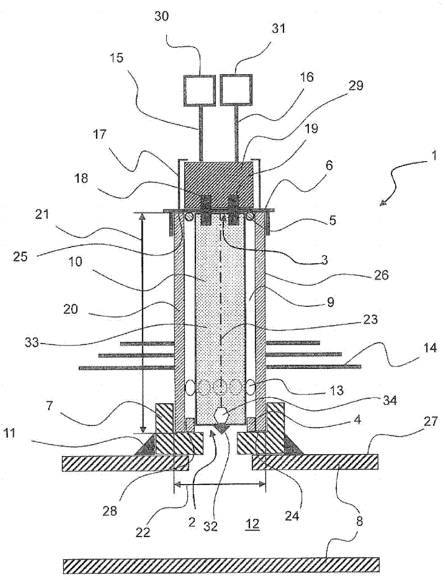
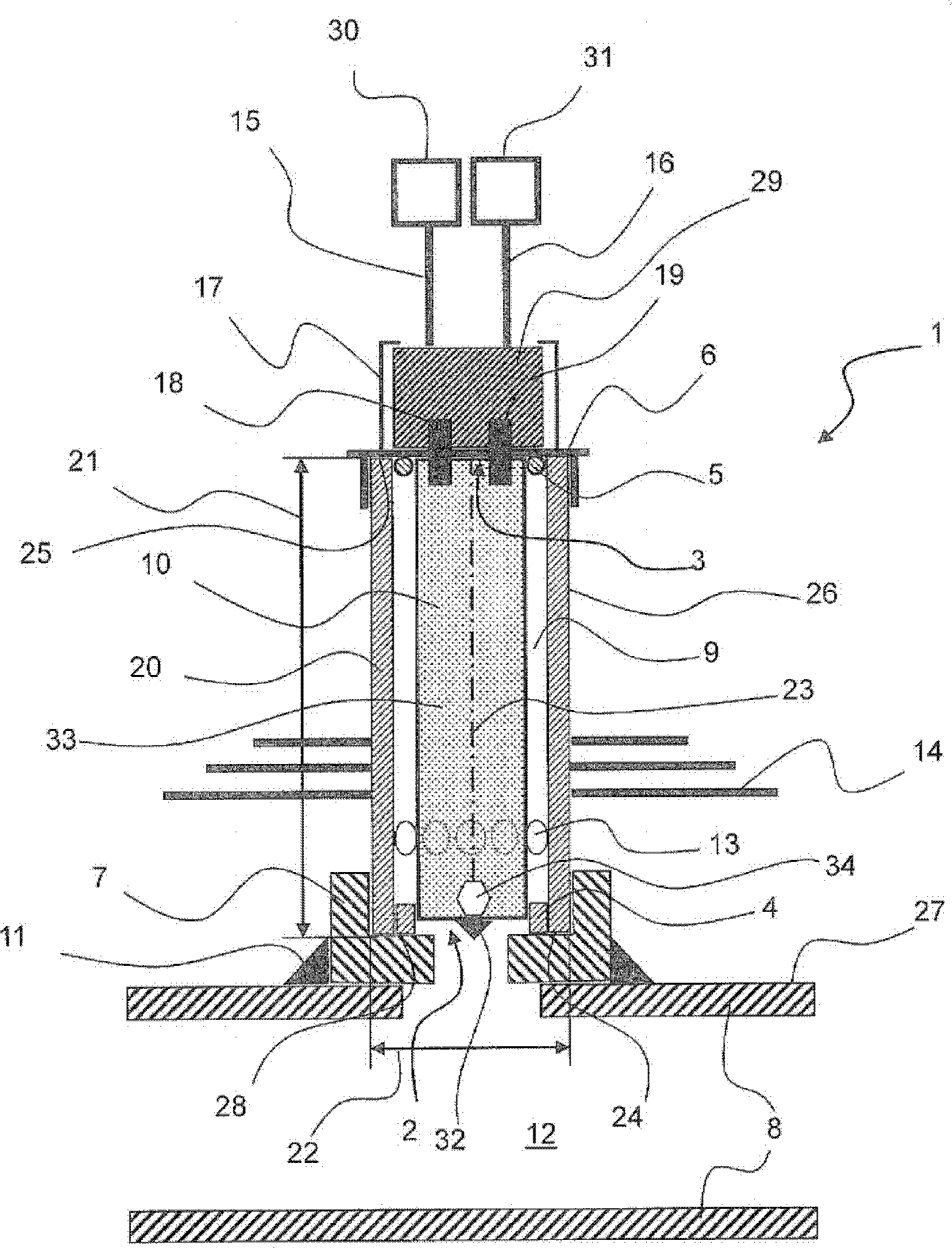
[0023] figure 1 The exhaust gas line 8 is shown, the connection piece 7 being attached to the outer wall 27 of the exhaust gas line 8 by means of a welded joint 11 . This connecting piece 7 has a receptacle 28 for the injector mount 1 . For this purpose, the receptacle 28 of the connection piece 7 may have a thread (not shown). The diameter of the receptacle 28 corresponds substantially to the width 22 of the housing 20 of the injector mount 1 . In this embodiment, the housing 20 is of tubular design. The housing 20 of the injector mount 1 also has a length 21 extending from the first opening 2 to the second opening 3 or from the first front face 24 in the direction of a central axis 23 shown here as the centerline to the second front face 25 . The injector chamber 9 is arranged in the housing 20 . The injector chamber 9 is connected via the first opening 2 to the exhaust gas carrying area 12 of the exhaust gas line 8 . The second opening 3 can be repeatedly closed by th...


PUM


Abstract

The invention relates to an injector mount (1) for accommodating at least one injector (10) completely, comprising a housing (20) having at least one injector chamber (9), wherein the at least one injector chamber (9) comprises a first opening (2) and a second opening (3). It is possible for the first opening (2) of the injector chamber (9) to be connected to a region (12) of an exhaust line (8) that conducts exhaust gas, and for the second opening (3) of the injector chamber (9) to be closed repeatedly by means of a closure (6).

Description

technical field [0001] The invention relates to an injector mount for receiving an injector. Such injectors are particularly useful for adding reducing agent to the exhaust system. Background technique [0002] Methods for reducing nitrogen oxide components in exhaust gases from internal combustion engines by selective catalytic reduction (SCR) are known. In this process, substances with a direct reducing effect, such as ammonia or its precursors, are injected into the exhaust gas. An example of a precursor that can be used is aqueous urea. During selective catalytic reduction, ammonia is converted together with nitrogen monoxide and nitrogen dioxide into molecular nitrogen and water. Selective catalytic reduction takes place in the SCR catalytic converter. [0003] Reductant is introduced into the exhaust gas through injectors. Typically, such injectors have a fastening device by means of which the injector is fastened to the exhaust gas line. Therefore, the injector ...

Claims


Application Information

Patent Timeline
IPC IPC(8): F01N3/36F01N3/20
CPCF01N3/2066F01N3/36F01N2610/02F01N2610/1453Y02T10/12F01N3/10F01N3/20
Inventor 简·霍奇森斯文·舍佩尔斯
Owner EMITEC GESELLSCHAFT FUR EMISSIONSTECHNOLOGIE MBH
Learn More