
Enhanced ultrasonic imaging probe using flexural-mode piezoelectric transducer

A technology of ultrasonic imaging and piezoelectric ultrasound, which is applied in the direction of vibrating fluids, surgery, catheters, etc., can solve the problems of large array elements and high-density integration that are not feasible

Inactive Publication Date: 2012-09-19
RES TRIANGLE INST +1
View PDF5 Cites 20 Cited by
  • Summary
  • Abstract
  • Description
  • Claims
  • Application Information

AI Technical Summary

Problems solved by technology

But this typically requires solder bumping, which is a higher temperature process (around 300°C), and high density integration is not feasible due to the large array element size (minimum 200-300 micron pitch)

Method used


Image

  • Enhanced ultrasonic imaging probe using flexural-mode piezoelectric transducer
  • Enhanced ultrasonic imaging probe using flexural-mode piezoelectric transducer
  • Enhanced ultrasonic imaging probe using flexural-mode piezoelectric transducer

Examples


example

[0103] The method of generating an enhanced received signal from an ultrasonic piezoelectric transducer is further described with reference to the following examples.

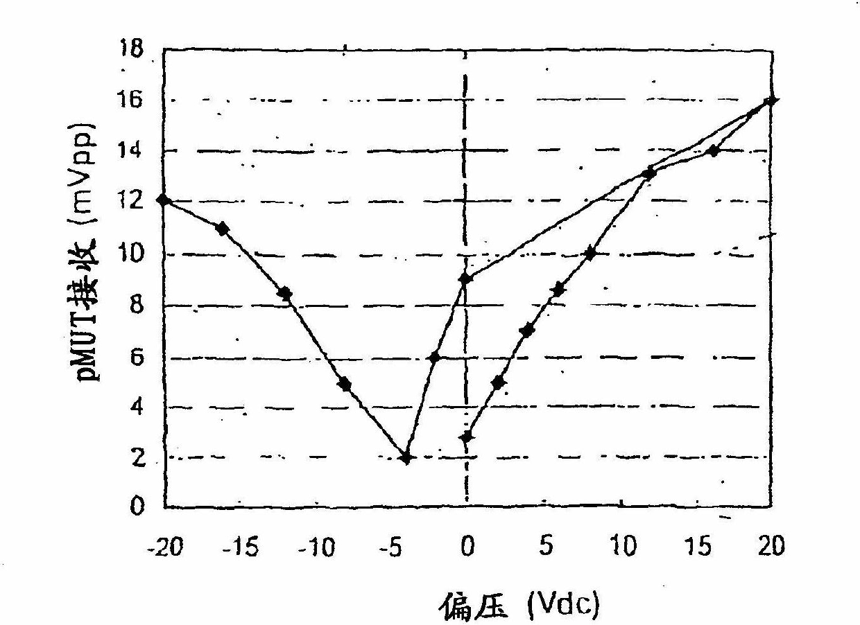
[0104] A single pMUT element experiences a DC bias from -20Vdc to +20Vdc. The acoustic signal provided by a separate piston transducer is directed towards the pMUT element. The signal received by the pMUT element is measured as a function of the applied DC bias. refer to figure 1 , which shows a graph depicting the peak-to-peak received signal (in mV) versus bias voltage. figure 1 The data for , represent the output response of the pMUT element for different levels of DC bias. The DC bias goes from 0V to +20V, back to 0V, and then from 0V to -20V. The received signal (mV) was recorded at each DC bias increment. figure 1 It is shown that, in this particular piezoelectric film, the optimal DC bias for the coercive field level increases the receiver sensitivity. When the DC bias voltage is close to the coerc...


PUM


Abstract

The invention relates to an enhanced ultrasonic imaging probe using a flexural-mode piezoelectric transducer and discloses a method for generating an enhanced receiving signal by the piezoelectric ultrasonic transducer. The method comprises the following steps of: supplying the piezoelectric ultrasonic transducer, wherein the piezoelectric ultrasonic transducer comprises a piezoelectric element which can work under a flexural mode; receiving an acoustic signal by the piezoelectric element; applying DC (Direct Current) bias voltage to the piezoelectric element before receiving the acoustic signal and / or while receiving the acoustic signal; and generating the enhanced receiving signal by the piezoelectric element, and using the enhanced receiving signal as a result of receiving the acoustic signal by the piezoelectric element. The invention also discloses an imaging probe based on a pMUT (Piezoelectric Micro-processing Ultrasonic Transducer) using the method.

Description

[0001] This application is a divisional application of a Chinese invention patent application with a filing date of November 3, 2006, an application number of 200680056647.X, and an invention title of "Enhanced Ultrasonic Imaging Probe Using a Flexural Mode Piezoelectric Transducer". technical field [0002] The present invention relates to a method of generating an enhanced flexure mode signal by a piezoelectric transducer and an ultrasound imaging probe using the method. Background technique [0003] Ultrasound transducers are particularly useful for non-invasive as well as in vivo medical diagnostic imaging. Conventional ultrasound transducers are typically fabricated from piezoelectric ceramic materials such as lead zirconate titanate (PZT) or PZT polymer composites, which are sliced ​​or laser cut to form arrays arranged in one or two dimensions multiple individual components. Acoustic lenses, matching layers, backing layers, and electrical interconnects (eg flex cable...

Claims


Application Information

Patent Timeline
Patent Type & Authority Applications(China)
IPC IPC(8): A61B8/12B06B1/06
Inventor D·道施O·冯拉姆J·卡斯泰卢奇
Owner RES TRIANGLE INST
Learn More