

Internal heating and pressurizing pipe distortion rectification device and method
A technology of internal heating and pressurized tubes, which is applied in the direction of metal processing equipment, forming tools, manufacturing tools, etc., can solve the problems of easily changing mold shape and size, achieve the effects of improving forming performance, avoiding environmental pollution, and reducing production costs
- Summary
- Abstract
- Description
- Claims
- Application Information
AI Technical Summary
Problems solved by technology
Method used
Image

Examples
specific Embodiment approach 1
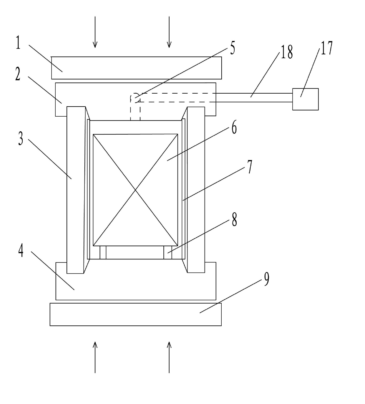
[0020] Specific implementation mode one: combine figure 1 To illustrate this embodiment, a pipe shape correction device using internal heating and pressurization in this embodiment includes a booster cylinder 17 and a pressurized tube 18, and the pipe shape correction device also includes an upper slider 1, an upper mold base 2, The mold insert 3, the lower mold base 4, the heating source 6, the support block 8 and the lower table 9, the lower table 9 is horizontally arranged on the ground, and the upper slider 1, the upper mold base 2 and the lower mold base 4 are sequentially arranged from top to bottom Set on the lower table 9, the mold insert 3 is embedded between the upper mold base 2 and the lower mold base 4, the support block 8 is arranged on the lower table 9 in the mold insert 3, and the heating source 6 is arranged on the support block 8, And the connecting end between the heating source 6 and the outside is sealed on the support block 8, the upper die base 2 is pro...
specific Embodiment approach 2
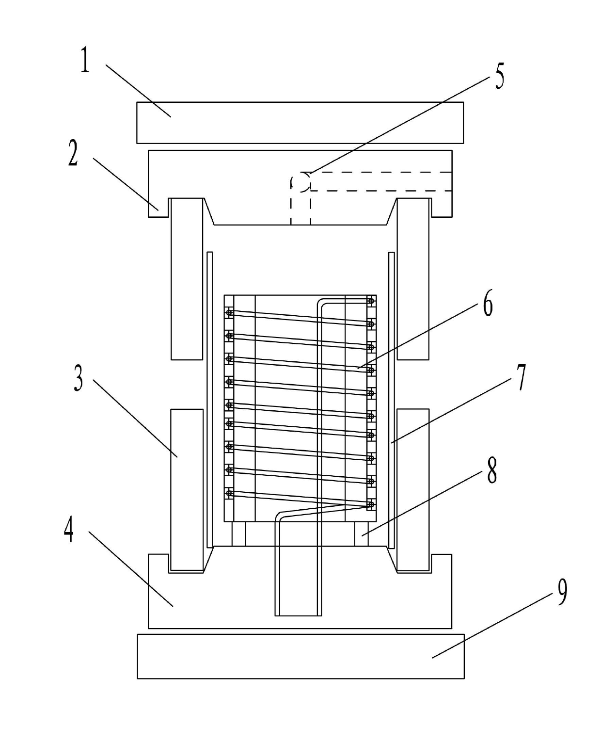
[0021] Specific implementation mode two: combination Figure 6 The present embodiment will be described. The heat source 6 of the present embodiment is an induction coil 10 wound in a helical shape. With such arrangement, the pipe blank 7 is heated by induction heating, and the heating speed is fast, and the local temperature control of the pipe material can be realized by adjusting the shape, size and position of the induction coil 10 . Other components and connections are the same as those in the first embodiment.
specific Embodiment approach 3
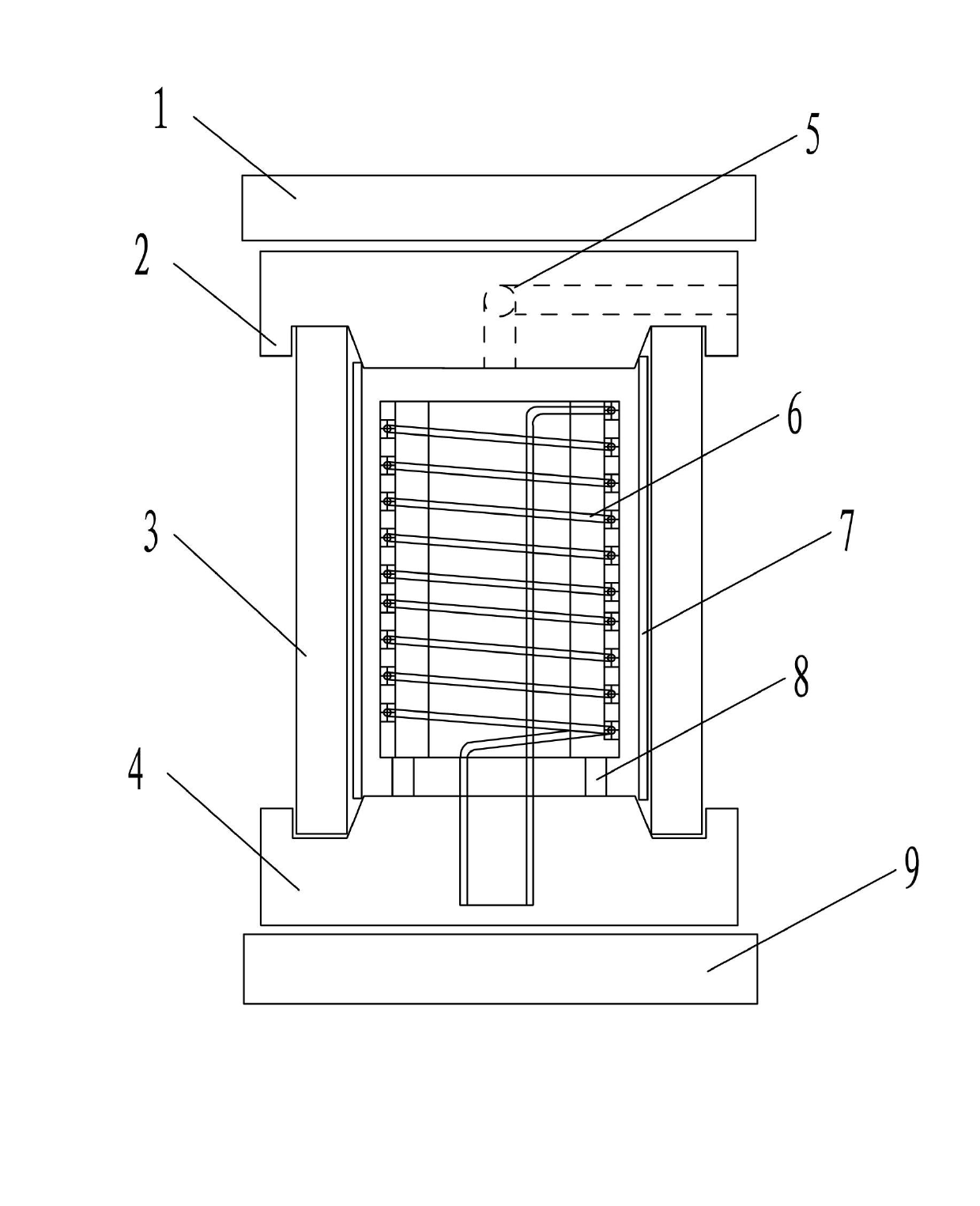
[0022] Specific implementation mode three: combination Figure 7 To illustrate this embodiment, the heating source 6 of this embodiment includes an induction coil 10 and a solid mandrel 11 , the induction coil 10 is helically wound on the solid mandrel 11 , and the solid mandrel 11 is set on the support block 8 . With such arrangement, the heated solid mandrel 11 heats the tube blank 7 by means of radiation, and the heating speed is faster than the heating by only the induction coil 10, and the temperature of the tube blank is more stable. Other compositions and connections are the same as those in Embodiment 1 or 2.
PUM
| Property | Measurement | Unit |
|---|---|---|
| The inside diameter of | aaaaa | aaaaa |
Abstract
Description
Claims
Application Information