Electrotype splicing method

An electroforming plate, electroforming technology, applied in the field of electroforming plate making

Inactive Publication Date: 2012-09-19
HUBEI LHTC ANTI COUNTERFEITING TECH CO LTD
View PDF7 Cites 9 Cited by
  • Summary
  • Abstract
  • Description
  • Claims
  • Application Information

AI Technical Summary

Problems solved by technology

[0002] Due to the limitation of the size of the lithography machine and the lithography process, the masters produced are all small-sized unit nickel plates, and there is only one unit on the unit nickel plate The pattern cannot be used in the production of the current molding machine. It is necessary to cover the entire nickel plate made of the unit nickel plate with the size of the molding machine roll on the roll, and finally transfer it to the film by hot pressing, usually by copying The method of cutting and manually splicing multiple unit nickel plates, first stick the double-sided tape on the plexiglass plate, and then manually paste the unit nickel plates one by one into a large plate of the required size, and splicing together The graphics are copied again, but because it is difficult to ensure the uniformity around each plate due to double-sided adhesive paste, the plate seam after splicing will become larger, which will affect the connection strength of the plate seam after electroforming; due to the order and method of splicing , the splicing accuracy is difficult to guarantee, the human factor is greatly affected, and the efficiency is low. Therefore, there is no ideal splicing method for the splicing method of large-size master plates.

Method used


Image

  • Electrotype splicing method
  • Electrotype splicing method
  • Electrotype splicing method

Examples


Embodiment 1

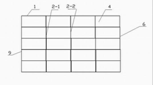
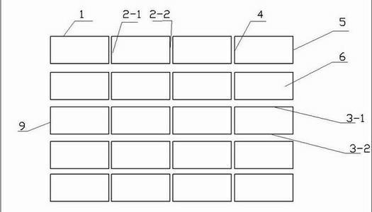
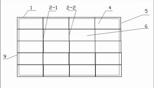
[0035] c. Cut the nickel plate 1 of the unit nickel plate 1 with the holographic pattern affixed with the middle adhesive protective film 4 according to the same specification with a cutting knife to align any one of the opposite two sides 2-1, 2-2;

[0036] d. The cut edges of the four cut nickel plates 1 are manually spliced ​​one by one, and the seams are tightly connected with adhesive tape on the above-mentioned intermediate adhesive protective film 4 to form a A unit group 6;

[0037] e. Put the connected unit group 6 on the platform with the back facing up, and paste all the nickel plate seams of the back unit with the special electroforming tape; tear off the middle-adhesive protective film 4 on the front;

[0038] f. Put the unit group 6 into the electroforming solution for electroforming connection; the thickness of the casting plate is required to reach more than 100um to ensure the connection strength of the plate seam;

[0039] g. The unit group 6 that has been e...

Embodiment 2

[0049] c. trimming any one of the relative two sides 2-1, 2-2 of the unit nickel plate 1 with the holographic pattern pasted with the middle adhesive protective film 4 according to the same specification with a cutting knife, such as figure 2 shown;

[0050] d. Carry out manual one-line splicing of the cut edges of the 4 pieces of the unit nickel plate 1 that have been cut, and use adhesive tape to tightly connect the seams on the above-mentioned medium-adhesive protective film 4, as shown in figure 2 Constitute a unit group 6;

[0051] e. Put the connected unit group 6 on the platform with the back facing up, and paste all the nickel plate seams of the back unit with the special electroforming tape; tear off the middle-adhesive protective film 4 on the front;

[0052] f. Put the unit group 6 into the electroforming solution for electroforming connection; the thickness of the casting plate is required to reach more than 100um to ensure the connection strength of the plate s...


PUM


Abstract

The invention relates to an electrotyping technology in holographic anti-counterfeiting printing, in particular to an electrotype splicing method, in which a large-area holographic nickel plate with high positioning precision and an optional area is formed by unit nickel plates through splicing. The unit nickel plates are obtained through replication, and medium viscosity protective film is adhered to the front surface of each unit nickel plate; any two opposite edges of each unit nickel plate are evenly cut by a plate cutter according to identical specifications; the cut edges are spliced linearly by hand, and the joints are connected through adhesive tape, so as to form a unit group; the other pair of opposite edges of each unit group is cut by the plate cutter according to the identical specifications, so that the upper and the lower edges of each unit group are evenly cut, and a large plate can be formed by the unit groups through splicing; and the plate joints on the back of the large plate are pasted through special electrotyping tape, the medium viscosity protective film is torn off, and the large plate is connected through electrotyping. The electrotype thickness is required to be above 100 microns, the connection strength is guaranteed, the splicing quality and efficiency are improved, effects from human factors are reduced, the edge cutting is controlled, fixed reserved edges are kept, and the cutting precision is ensured.

Description

technical field [0001] The invention relates to an electroforming plate-making technology in holographic anti-counterfeiting printing, in particular to an electroforming plate splicing method. Background technique [0002] Due to the limitation of the size of the photolithography machine and the limitation of the photolithography process, the current masters are all small-sized unit nickel plates. There is only one unit pattern on the unit nickel plate, which cannot be used for the production of the current molding machine. The plate is made of a whole nickel plate that matches the size of the plate roll of the molding machine and is coated on the plate roll, and finally transferred to the film by hot pressing. Usually, the method of duplicating multiple nickel plates for cutting and manual splicing is adopted. First Stick the double-sided tape on the plexiglass plate, and then manually paste the unit nickel plate one by one into a large plate of the required size, and then ...

Claims


Application Information

Patent Timeline
Patent Type & Authority Applications(China)
IPC IPC(8): C25D2/00
Inventor 吴德平
Owner HUBEI LHTC ANTI COUNTERFEITING TECH CO LTD
Why Eureka
Try Eureka