
Power-generation-type deceleration strip

A speed bump and power generation technology, applied in the field of power speed speed bump, can solve the problems of effective utilization, loss, waste, etc., and achieve the effects of high power generation efficiency, short transmission path and simple structure

Inactive Publication Date: 2014-05-21
SOUTHWEST JIAOTONG UNIV
View PDF5 Cites 0 Cited by
  • Summary
  • Abstract
  • Description
  • Claims
  • Application Information

AI Technical Summary

Problems solved by technology

However, the kinetic energy lost when the vehicle passes through the speed bump is usually not effectively utilized, and is wasted and lost.

Method used


Image

  • Power-generation-type deceleration strip
  • Power-generation-type deceleration strip
  • Power-generation-type deceleration strip

Examples


specific Embodiment approach

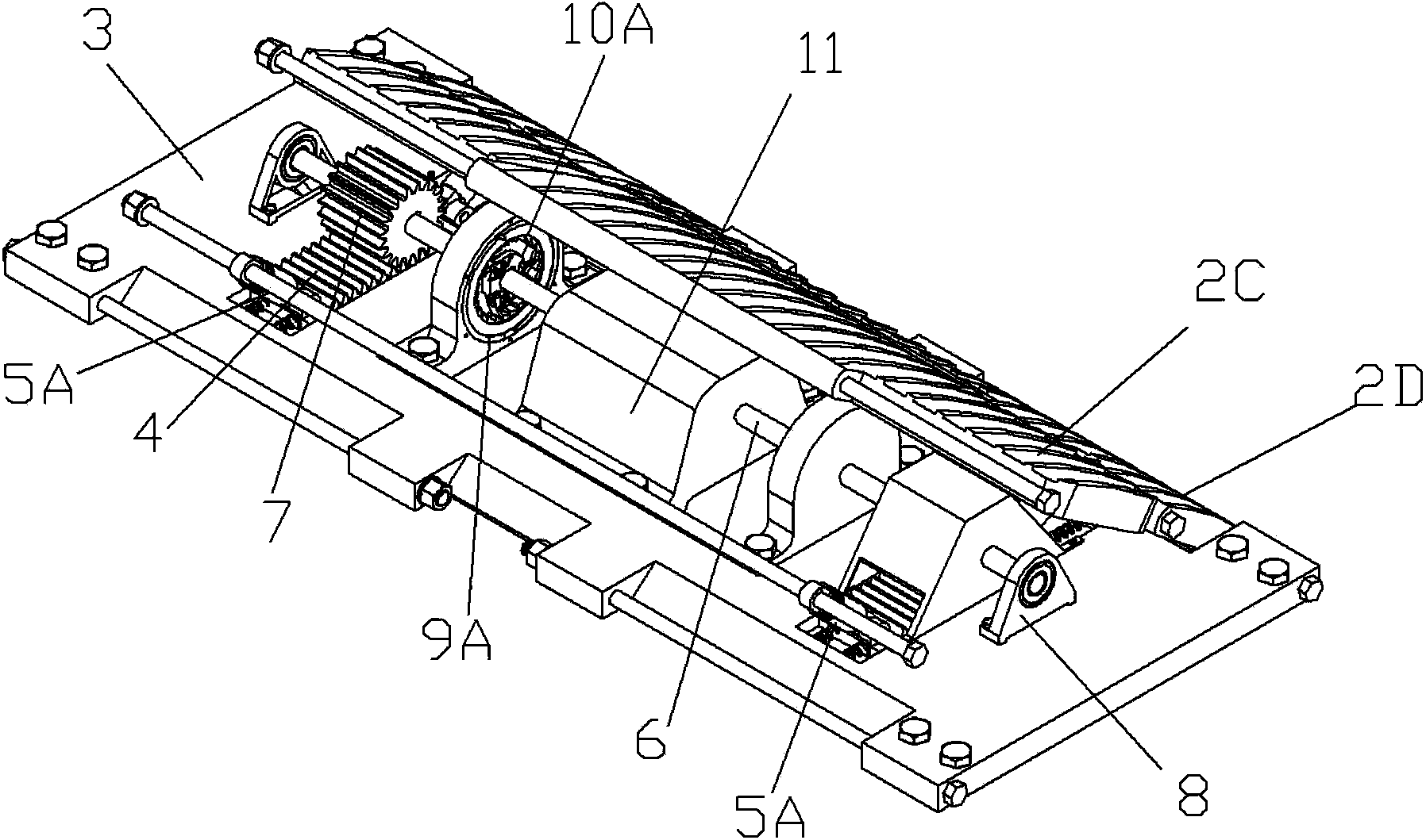
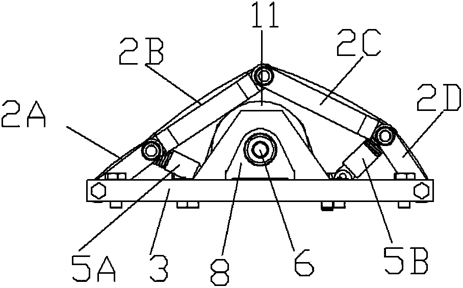
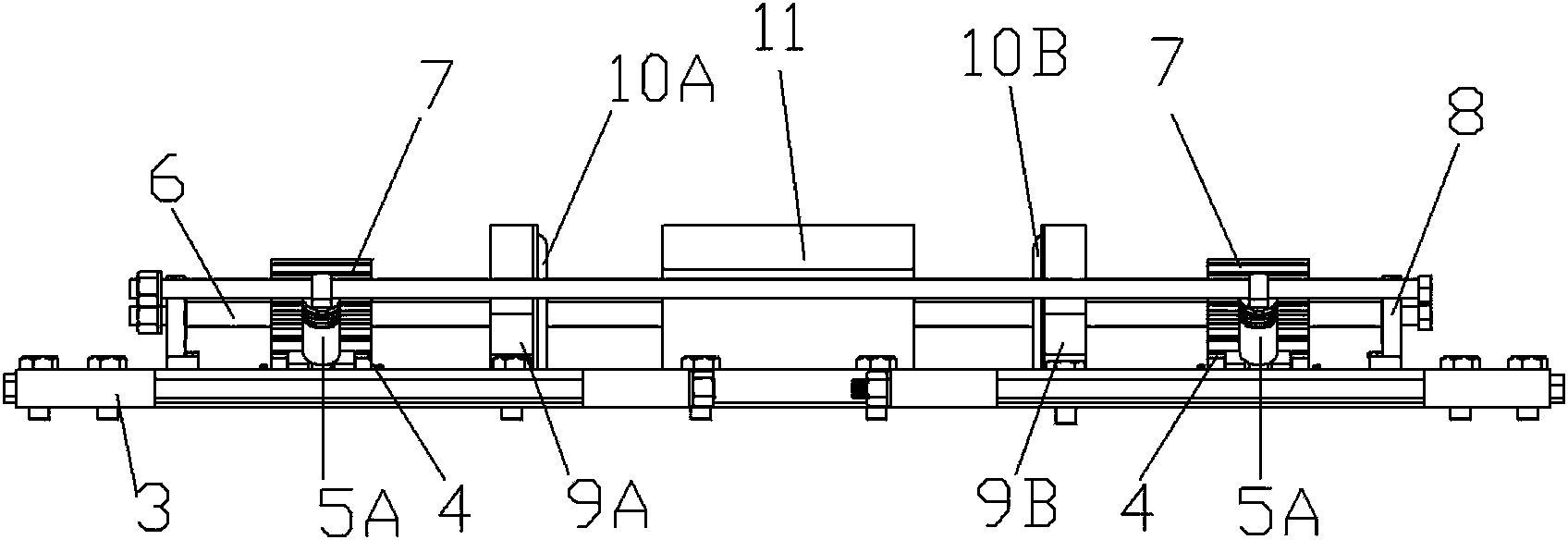
[0018] Figure 1-3 It is shown that a specific embodiment of the present invention is: a power generation speed reduction belt, which is composed of: a grounding plate 3 fixed on the ground, a front cover 2A, a front cover 2B, a rear cover 2C, The back cover-2D is sequentially hinged to form an arched cavity; the ground plate 3 in the cavity is provided with a longitudinal rack 4, and the front end of the rack 4 is connected to the front cover-2A, the front cover through the elastic connector-5A The hinge shaft between the plate two 2B is hinged, and the rear end of the rack 4 is hinged with the hinge shaft between the rear cover one 2D and the rear cover two 2C through the elastic connector two 5B; the rack 4 meshes with the gear 7 above it, so The gear shaft 6 of the gear 7 is installed on the grounding plate 3 through the bearing seat 8;

[0019] The gear shaft 6 is also equipped with an inner meshing ratchet pawl mechanism one 10A and an inner meshing ratchet pawl mechani...


PUM


Abstract

The invention provides a power-generation-type deceleration strip which is characterized in that a grounding plate, a front cover plate I, a front cover plate II, a rear cover plate II and a rear cover plate I are sequentially hinged to form an arched hollow cavity, wherein the grounding plate is provided with a vertical rack; the front end of the rack is hinged with a hinging shaft between the front cover plate I and the front cover plate II through an elastic connecting piece I; the back end of the rack is hinged with a hinging shaft between the rear cover plate I and the rear cover plate II through an elastic connecting piece II; the rack is engaged with a gear at the upper side; the gear shaft of the gear is mounted on the grounding plate through a bearing seat; the gear shaft is further provided with an inner engaging ratchet wheel pawl mechanism I and an inner engaging ratchet wheel pawl mechanism II, and the pawl directions of the inner engaging ratchet wheel pawl mechanisms I and II are opposite; the inner engaging ratchet wheel pawl mechanism I is sleeved in the inner cavity of a stator I wound by a coil so as to form a generation device I; and the inner engaging ratchet wheel pawl mechanism II is sleeved in the inner cavity of a stator II wound by a coil so as to form a generation device II. The deceleration strip disclosed by the invention can convert kinetic energy lost by an automobile into electric energy and has the advantages of simple structure, low cost, safety and reliability in use and no pollution.

Description

technical field [0001] The invention relates to a speed reduction belt, in particular to a power generation speed reduction belt. Background technique [0002] In order to reduce the speed of the vehicle, a speed bump with a certain degree of elasticity will be arranged on the road surface. However, the kinetic energy lost when the vehicle passes through the speed bump is usually not effectively utilized, and is wasted and lost. Contents of the invention [0003] The purpose of the present invention is to provide a power generation speed bump, which can not only reduce the vibration and noise when the car passes the speed bump, but also collect the kinetic energy lost by the car and convert it into electric energy for storage and utilization. Simple, low cost, safe and reliable in use, and pollution-free. [0004] The technical solution adopted by the present invention to realize the purpose of the invention is: a power generation speed reduction belt, which is composed ...

Claims


Application Information

Patent Timeline
Patent Type & Authority Patents(China)
IPC IPC(8): E01F9/047F03G7/00E01F9/529
Inventor 高宏力张筱辰黄海凤郭亮文娟陈晨陈小莉吴枭徐东朱少成李超
Owner SOUTHWEST JIAOTONG UNIV
Learn More