Engine piston cooling device

A technology of piston cooling and piston cooling nozzles, which is applied in the cooling of engines, engine components, machines/engines, etc., can solve the problems of deterioration of HC emissions, reduced working reliability, and high failure rate of solenoid valves, so as to improve HC emissions, speed up Warm-up speed, the effect of improving fuel economy

Inactive Publication Date: 2012-09-19
GREAT WALL MOTOR CO LTD
View PDF5 Cites 6 Cited by
  • Summary
  • Abstract
  • Description
  • Claims
  • Application Information

AI Technical Summary

Problems solved by technology

[0003] At present, most of the engine piston cooling devices realize the injection of engine oil through the piston cooling nozzles installed on the main oil passage of the cylinder block, and rely on the pressure limiting valve of the piston cooling nozzles to control the action of the piston cooling nozzles; The piston can be effectively cooled, and the control pressure of the pressure limiting valve is generally set at about 200kPa. However, when the engine is cold started, the pressure in the main oil passage will generally reach above 500kPa. and combustion chamber overcooling, resulting in reduced combustion efficiency, poor fuel economy, deterioration of HC emissions, carbon deposits in the combustion chamber and other adverse consequences
Although the solenoid valve can be used to control the piston cooling device according to the working conditions of the engine, a large number of tests and data calibration are required, which prolongs the development cycle and increases the cost, and the high failure rate of the solenoid valve reduces its working reliability

Method used


Image

  • Engine piston cooling device
  • Engine piston cooling device
  • Engine piston cooling device

Examples


Embodiment Construction

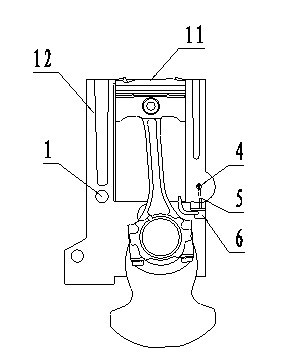
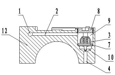
[0016] Referring to Fig. 1 and Fig. 2, the present invention includes a control valve 3, a cylinder block main oil passage 1, a cylinder block auxiliary oil passage 4, a communication oil passage 2, a cooling nozzle oil passage 5 and a piston cooling nozzle assembly 6, the control valve 3 Control its one-way opening and closing by sensing the temperature of the engine oil. The control valve 3 is installed at the end of the oil passage 2 between the main oil passage 1 of the cylinder block and the auxiliary oil passage 4 of the cylinder block. The main oil passage 1 of the cylinder block is connected to the engine The components of the lubrication system are connected, and the auxiliary oil passage 4 of the cylinder block communicates with the piston cooling nozzle assembly 6 through the cooling nozzle oil passage 5 .

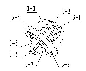
[0017] see image 3 , the control valve of the present invention consists of an induction body 3-1, a spring 3-2, a spring holder 3-3, a gasket 3-4, a push rod ...


PUM


Abstract

An engine piston cooling device is used for solving the cooling problem of an engine in different operating conditions and comprises a control valve, a cylinder body main oil passage, a cylinder body auxiliary oil passage, a communicating oil passage, a cooling nozzle oil passage and a piston cooling nozzle assembly, wherein the one-way open / close of the control valve is controlled by sending the engine oil temperature, the control valve is installed at the tail of the communicating oil passage between the cylinder body main oil passage and the cylinder body auxiliary oil passage, the cylinder body main oil passage is communicated with an engine lubrication system element, and the cylinder body auxiliary oil passage is communicated with the piston cooling nozzle assembly through the cooling nozzle oil passage. According to the invention, the oil injection action is jointly controlled by the control valve and the pressure limiting valve of the piston cooling nozzle assembly, so as to ensure that the piston part can achieve the optimal cooling effect in different operating conditions of the engine.

Description

technical field [0001] The invention relates to a cooling device, in particular to an engine piston cooling device with a control valve, belonging to the technical field of engines. Background technique [0002] In order to improve the fuel economy and power performance of the engine, new technologies such as turbocharging, in-cylinder direct injection, and high compression ratio are widely used, resulting in an increasingly high degree of strengthening of the engine, and an increasing heat load on the piston. Large; in order to effectively reduce the heat load of the piston and ensure its working reliability, most modern engines are equipped with a piston cooling device, which cools the bottom of the piston by spraying oil. [0003] At present, most of the engine piston cooling devices realize the injection of engine oil through the piston cooling nozzles installed on the main oil passage of the cylinder block, and rely on the pressure limiting valve of the piston cooling n...

Claims


Application Information

Patent Timeline
IPC IPC(8): F01P3/08
Inventor 史占军张梓龙王磊
Owner GREAT WALL MOTOR CO LTD
Why Eureka
Try Eureka