Supercharged engine air inlet pipe deflating system

A technology of supercharged engine and bleed system, applied in engine control, combustion engine, machine/engine, etc., can solve the problems of poor sealing performance of exhaust pipe system and complex structure of supercharging system, easy to achieve sealing problem and low fuel consumption , good burning effect

Inactive Publication Date: 2012-09-19
SHANGHAI JIAO TONG UNIV
View PDF5 Cites 6 Cited by
  • Summary
  • Abstract
  • Description
  • Claims
  • Application Information

AI Technical Summary

Problems solved by technology

However, the existing turbocharging systems cannot take into account the high and low speed conditions of the engine well.
[0003] After searching the existing technical literature, it is found that Chinese patent number ZL200410050996.3, patent name: a variable modular pulse conversion supercharging device for a turbocharged diesel engine, this patent technology provides an exhaust pipe in the exhaust pipe The device with continuously variable volume can better take into account the high and low speed conditions of the engine; but the change of the exhaust volume in the exhaust pipe is realized by moving the moving rod up and down, which requires adding a special The control mechanism is used to control the movement of the moving rod, so that the structure of the booster system becomes more complicated, and the sealing of the exhaust pipe system is also poor under high temperature conditions

Method used


Image

  • Supercharged engine air inlet pipe deflating system
  • Supercharged engine air inlet pipe deflating system
  • Supercharged engine air inlet pipe deflating system

Examples


Embodiment

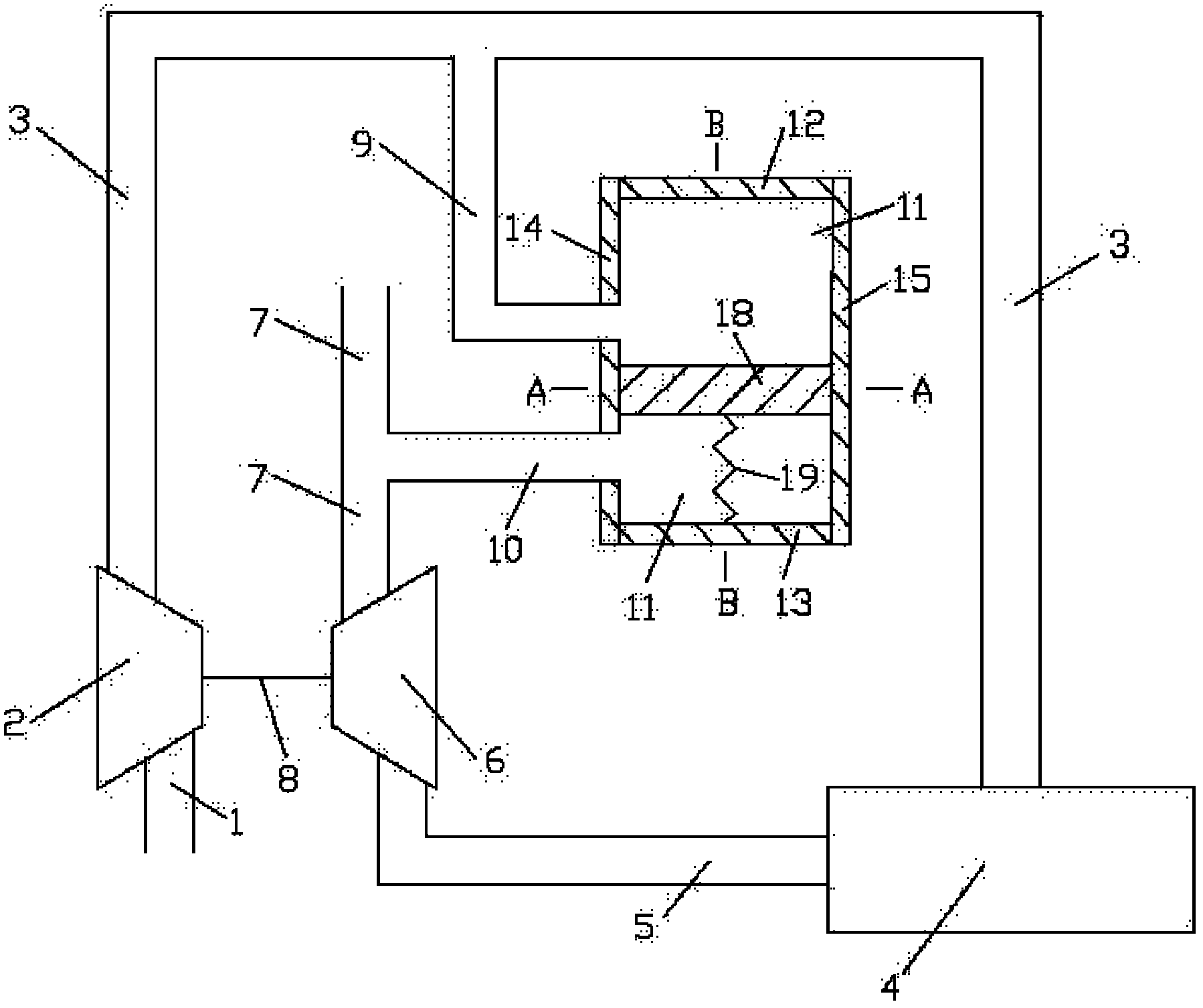
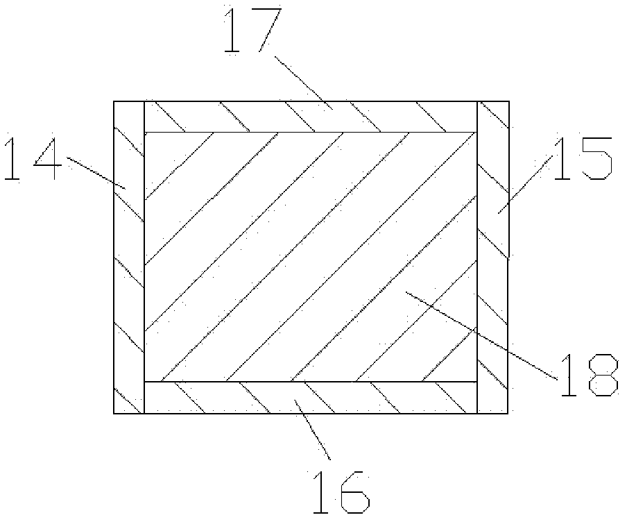
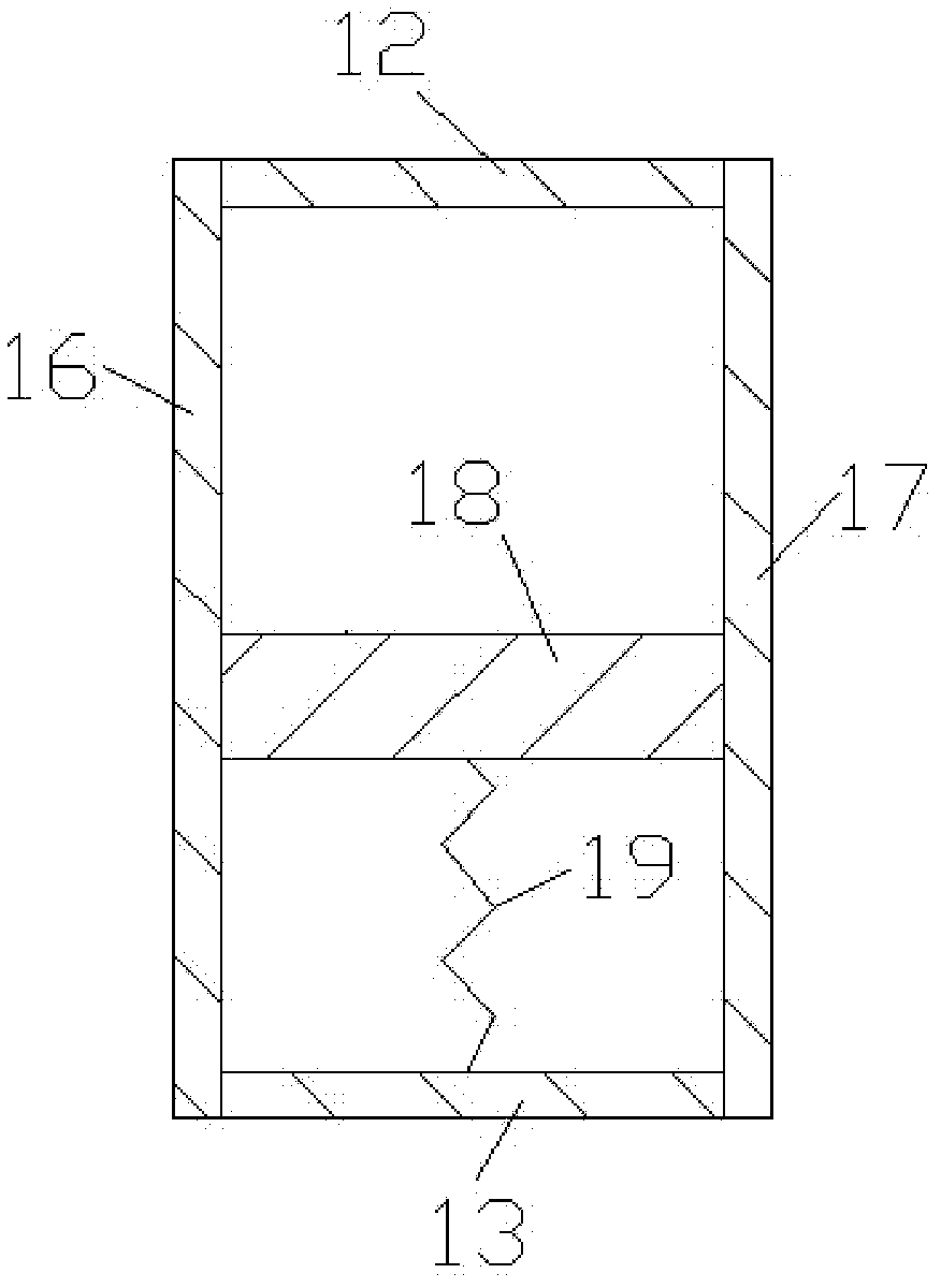
[0014] Such as figure 1 , figure 2 and image 3 Shown, the present invention comprises: compressor intake pipe 1, compressor 2, engine intake pipe 3, engine 4, engine exhaust pipe 5, turbine 6, turbine outlet pipe 7, connecting shaft 8, the first connecting pipe 9, the first Two connecting pipes 10, volume cavity 11, volume cavity upper wall 12, volume cavity lower wall 13, volume cavity left wall 14, volume cavity right wall 15, volume cavity front wall 16, volume cavity rear wall 17, moving body 18 and elastic Component 19, the compressor 2 is coaxially connected with the turbine 6 through the connecting shaft 8, the air inlet and outlet of the compressor 2 are connected with the air outlet of the compressor inlet pipe 1 and the air inlet of the engine inlet pipe 3 respectively, and the air inlet and outlet of the engine 4 Be respectively connected with the air outlet of engine air intake pipe 3, the air inlet of engine exhaust pipe 5, the air inlet and outlet of turbine ...


PUM


Abstract

The invention discloses a supercharged engine air inlet pipe deflating system in the technical field of internal combustion engines. The system comprises a compressor, a turbine, an engine, connecting pipes, a volume cavity, a moving body and an elastic part, wherein two ends of a first connecting pipe are respectively communicated with an engine air inlet pipe and a volume cavity left wall surface; two ends of a second connecting pipe are respectively communicated with an engine exhaust pipe and the volume cavity left wall surface; the moving body is arranged in the volume cavity and connected with a volume cavity lower wall surface through the elastic part. In the operating process, the moving body can move up and down in the volume cavity; the moving body moves upwards under low-speed working conditions of the engine, air compressed by the compressor totally enters the engine, the air inlet quantity of the engine is relatively increased, and a relative good combustion effect is achieved in each cylinder; and the moving body moves downwards under high-speed working conditions of the engine, part of air compressed by the compressor enters a turbine air outlet pipe, the air inlet quantity of the engine is relatively reduced, and the detonation pressure of each cylinder is reduced. The supercharged engine air inlet pipe deflating system is reasonable in design, simple in structure and suitable for a turbocharging system of the engine.

Description

technical field [0001] The invention relates to an air intake system in the field of internal combustion engines, in particular to a supercharged engine intake pipe discharge system of a turbocharged engine. Background technique [0002] With the development of modern society, people have higher and higher requirements on the power and economy of the engine. In the case of a certain displacement, the most effective way to increase the output power of the engine is to provide more fuel for combustion. It is easy to provide more fuel to the cylinder through the injector, but it is not so easy to provide the amount of air to match the increased amount of fuel at the same time; The effect is poor. When the fuel injection volume is constant and the cylinder air intake volume is large, the combustion is better, and the fuel consumption and emissions are lower. The traditional naturally aspirated engine completely relies on the vacuum formed in the cylinder to inhale air when th...

Claims


Application Information

Patent Timeline
Patent Type & Authority Applications(China)
IPC IPC(8): F02B37/00F02D9/02
CPCY02T10/144Y02T10/14Y02T10/12
Inventor 张贵阳乔信起庄健白金龙
Owner SHANGHAI JIAO TONG UNIV
Why Eureka
Try Eureka