Air intake manifold with integrated air track

A technology of intake manifold and air rail, which is applied in the field of intake manifold with integrated air rail, can solve problems such as engine acceleration pump air loss, achieve the effects of increasing intake air volume, convenient design, and reducing fuel consumption rate

Inactive Publication Date: 2012-09-19
CHERY AUTOMOBILE CO LTD
View PDF7 Cites 38 Cited by
  • Summary
  • Abstract
  • Description
  • Claims
  • Application Information

AI Technical Summary

Problems solved by technology

[0004] The present invention designs an intake manifold with an integrated air rail, which solves the problem of weak acceleration and large pumping loss when the engine is working at full load caused by the existing design method of the intake manifold. question

Method used


Image

  • Air intake manifold with integrated air track
  • Air intake manifold with integrated air track
  • Air intake manifold with integrated air track

Examples


Embodiment Construction

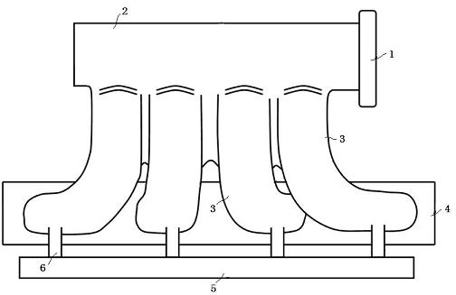
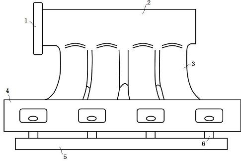
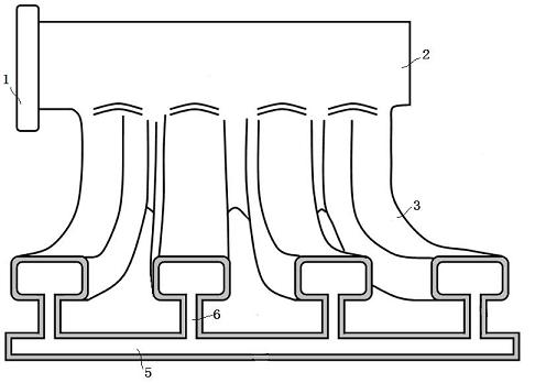
[0029] Below in conjunction with accompanying drawing, the present invention will be further described:

[0030] Figure 1 to Figure 3 It shows the structural schematic diagram and layout of an intake manifold with integrated air rail on a certain four-cylinder gasoline naturally aspirated engine, including engine intake throttle valve 1, intake manifold resonant cavity 2, four An intake manifold branch pipe 3, a connecting flange 4, an air rail 5 and four air rail connecting branch pipes 6; the air inlet at the upper end of each intake manifold branch pipe 3 communicates with the intake manifold resonant cavity 2, and each intake manifold The air outlet at the lower part of the branch pipe 3 is respectively connected to the cylinder head of each cylinder through the connecting flange 4; The lower end is close to the lower air outlet, and the other end is connected to the air rail 5; the air rail 5 is a closed cavity, and the air rail 5 communicates with each intake manifold ...


PUM


Abstract

The invention relates to an air intake manifold with an integrated air track, which comprises an air throttle (1) of an air inlet of an engine, a resonant cavity (2) of the air intake manifold, a plurality of branch pipes (3) of the air intake manifold, and a connecting flange (4), wherein the air throttle (1) at the upper end of each branch pipe (3) of the air intake manifold is communicated with the resonant cavity (2) of the air intake manifold; and air outlets at the lower parts of the branch pipes (3) of the air intake manifold are respectively connected with cylinder covers through the connecting flange (4). The air intake manifold is characterized in that the air intake manifold further comprises the air track (5) and a plurality of air track connecting branch pipes (6), wherein the air track connecting branch pipes (6) are corresponding to the branch pipes (3) of the air intake manifold one to one; and the air track (5) is communicated with the lower end of each branch pipe (3) of the air intake manifold through the corresponding air track connecting branch pipe (6). When the air intake manifold is fully loaded, resonance effects achieved at low rotating speeds and trough rotating speeds can be optimized, so that the air intake quantity is increased; when the air intake manifold is partially loaded, pumping loss of the engine is decreased, the fuel consumption rate is reduced, and the requirements for buses in different working conditions can be satisfied.

Description

technical field [0001] The invention belongs to the technical field of automobile engine intake manifolds, in particular to an intake manifold with integrated air rails. Background technique [0002] At present, the design of the intake manifold of the gasoline naturally aspirated engine for passenger cars mainly uses a certain length and diameter of the intake manifold and a certain volume of resonance chamber to form a resonant intake system, so that the natural frequency of the valve is the same as that of the valve. Intake cycle resonance, at a specific speed, before the intake valve closes, a large pressure wave is generated in the intake manifold, which increases the pressure of the intake manifold, thereby increasing the intake air volume. [0003] With this intake manifold design method, at full load, the resonance effect of the intake manifold may be used, and the engine performance may have a double-peak phenomenon. At the same time, in partial load, due to the in...

Claims


Application Information

Patent Timeline
Patent Type & Authority Applications(China)
IPC IPC(8): F02M35/104F02D9/08
Inventor 金晖王伟杨国玺
Owner CHERY AUTOMOBILE CO LTD
Why Eureka
Try Eureka