Cyclone-type wind power generation wind tunnel

A cyclone and wind tunnel technology, applied in the field of wind power generation wind tunnel and cyclone wind power generation wind tunnel, can solve the problems of low wind energy density value, low power generation power of a single wind power equipment, and can not be applied to power generation in the surrounding area of ​​the city, so as to achieve wind energy The effect of increasing density and increasing power generation efficiency

Active Publication Date: 2012-09-19
钟林贵
View PDF4 Cites 2 Cited by
  • Summary
  • Abstract
  • Description
  • Claims
  • Application Information

AI Technical Summary

Problems solved by technology

[0003] The purpose of the present invention is to solve the problems of low wind energy density value in natural conditions of existing wind power generation wind tunnels, low generating power of single wind power equipment, and inability to apply to power generation in surrounding areas of cities, and further provide a cyclone type wind power generation wind tunnel

Method used


Image

  • Cyclone-type wind power generation wind tunnel
  • Cyclone-type wind power generation wind tunnel
  • Cyclone-type wind power generation wind tunnel

Examples


specific Embodiment approach 1

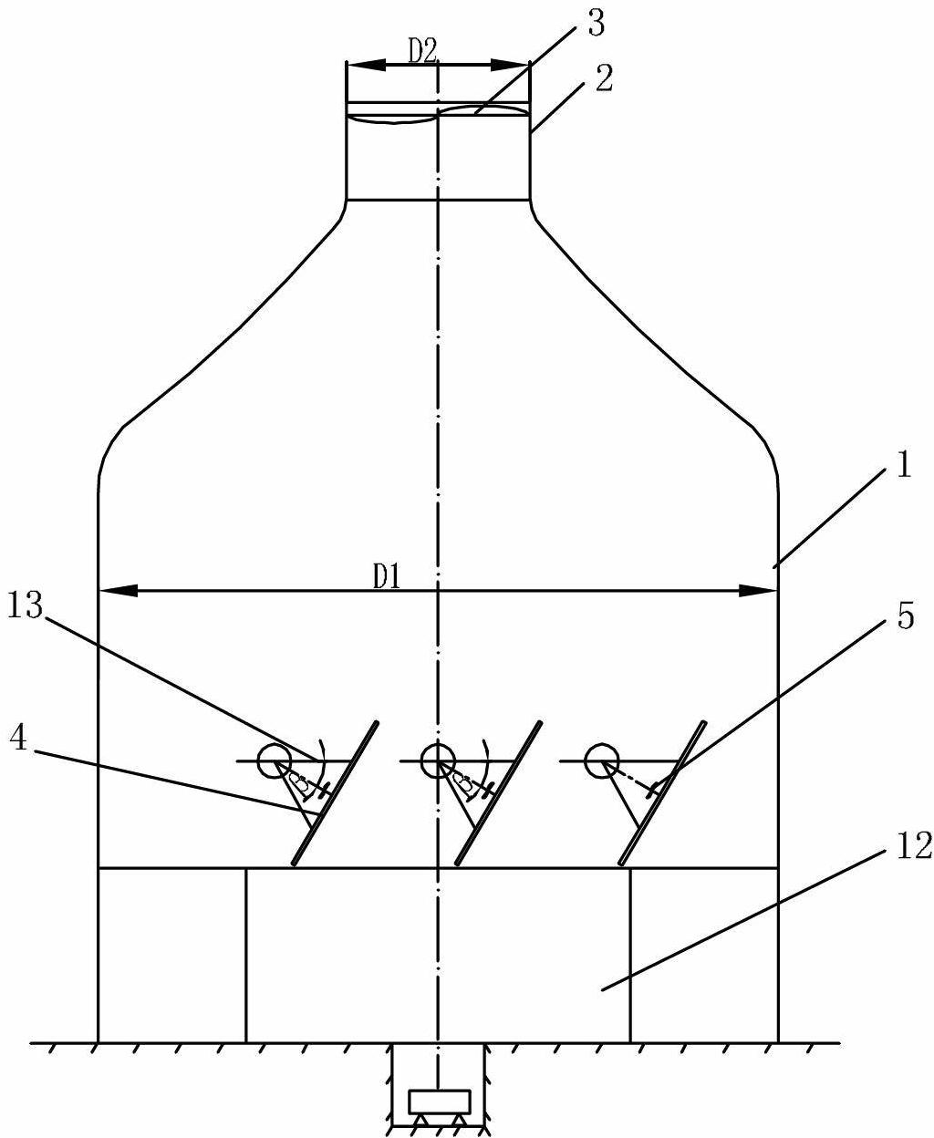
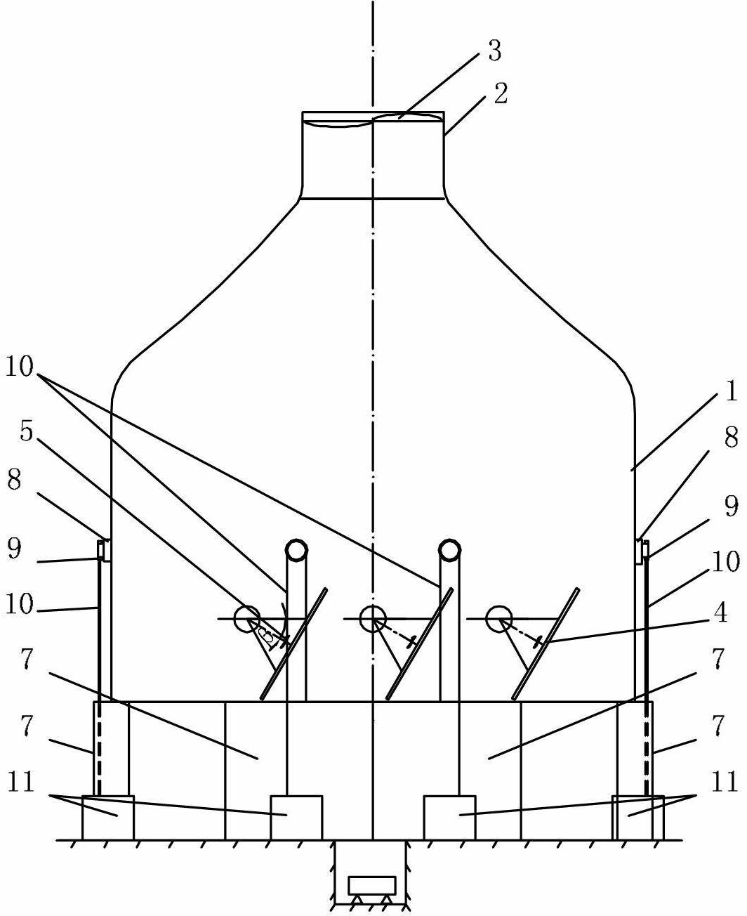
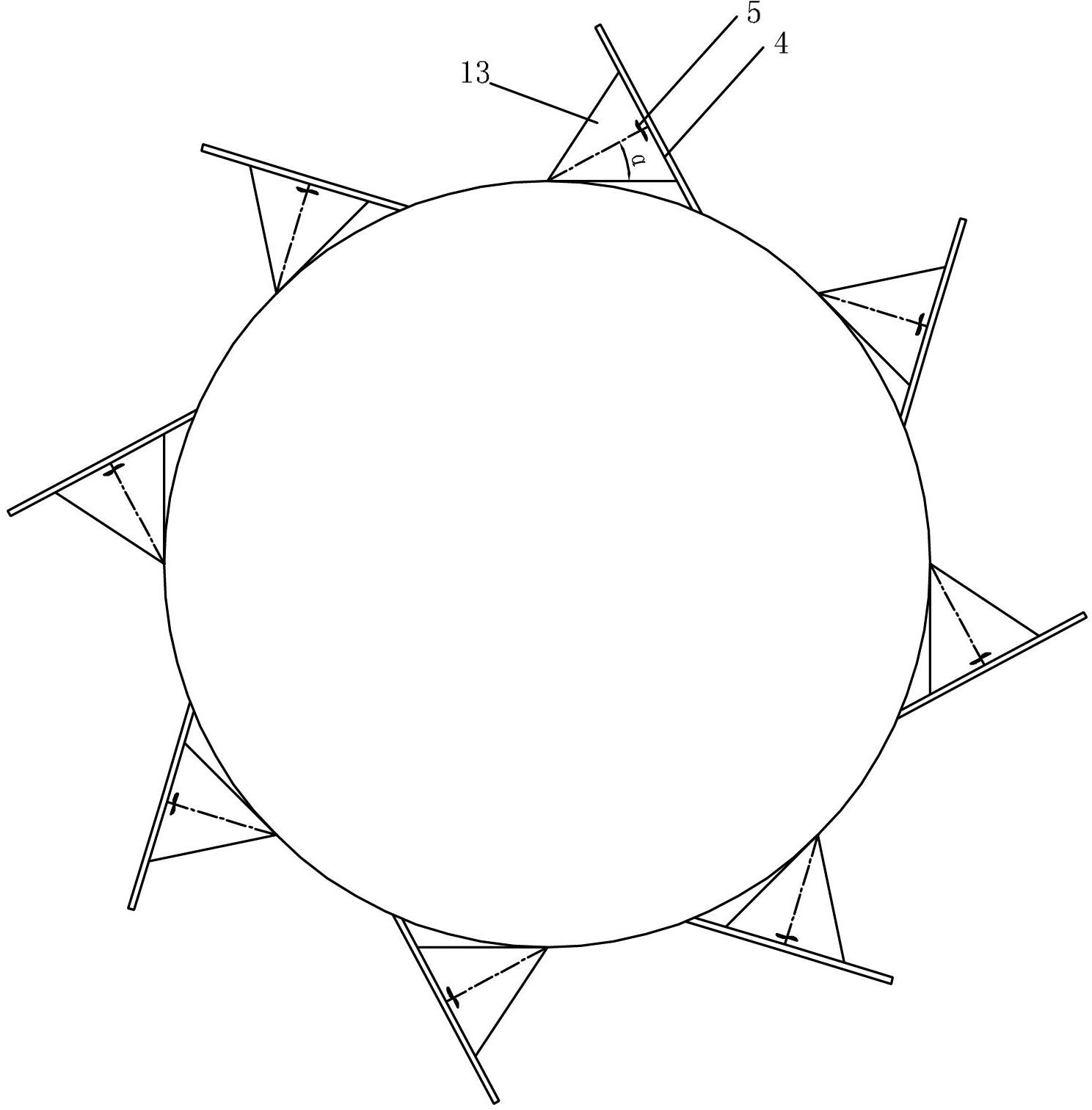
[0007] Specific implementation mode one: combine figure 1 , image 3 with Image 6 Describe this embodiment, the cyclone type wind power generation wind tunnel of this embodiment includes a draft hood 1, a wind tunnel 2, a wind wheel 3, a plurality of aperture type air volume control valves 4, a plurality of wind compensating fans 5 and a plurality of wind compensators 13. The wind hood 1 and the wind tunnel 2 are arranged coaxially from bottom to top, the wind wheel 3 is installed at the outlet end of the wind tunnel 2, and the ratio of the diameter D1 of the wind hood 1 to the diameter D2 of the wind tunnel 2 is 2.5 to 9 In between, a plurality of openings are provided on the wind-inducing hood 1, and the openings are arranged in a circular array. A wind compensator 13 is installed at each opening. 4 is installed at the inlet end of the wind compensator 13.

specific Embodiment approach 2

[0008] Specific implementation mode two: combination image 3 The present embodiment will be described. The number of wind power compensating blowers 5 in this embodiment is eight. Wind compensation is more reasonable. Other compositions and connections are the same as in the first embodiment.

specific Embodiment approach 3

[0009] Specific implementation mode three: combination figure 1 To describe this embodiment, the cyclone-type wind power generation wind tunnel of this embodiment further includes a wind collection adjustment device 12 , and the wind collection adjustment device 12 is installed at the lower end of the wind induction hood 1 . Adjust the air intake according to the wind speed and direction of the external environment. Other compositions and connections are the same as those in Embodiment 1 or Embodiment 2.


PUM


Abstract

The invention discloses a cyclone-type wind power generation wind tunnel, which relates to a wind power generation wind tunnel. The cyclone-type wind power generation wind tunnel aims to solve the problems of low natural-state wind energy density value and low stand-alone power generation power of wind power equipment of the traditional wind energy adding density device and also solve the problem that the traditional wind energy adding device cannot be used for generating power for areas around the city. The cyclone-type wind power generation wind tunnel comprises an air induction hood, a wind tunnel, a wind wheel, a plurality of aperture-type wind quantity regulation valves, a plurality of wind power compensation fans and a plurality of wind power compensators, wherein the air induction hood and the wind tunnel are coaxially arranged from bottom to top; the wind wheel is installed on the outlet end of the wind tunnel; a ratio of the diameter of the air induction hood to the diameter of the wind tunnel is 2.5-9; the air induction hood is provided with a plurality of holes; the holes are arranged annularly; and each hole is provided with a wind power compensation fan. The cyclone-type wind power generation wind tunnel is used for wind power generation.

Description

technical field [0001] The invention relates to a wind tunnel for wind power generation, in particular to a cyclone-type wind tunnel for wind power generation, and belongs to the technical field of wind power generation. Background technique [0002] Wind energy resources are abundant on the earth. China's wind energy reserves are 2.53 billion MW, and the effective wind energy density of coastal and coastal islands is greater than 200W / m 2 , the effective wind energy density on land is 100-200W / m 2 The effective wind energy density of land and mountains is between 300 and 700W / m 2 between. Current technical status: The effective wind energy density value of wind power generation is low, and the utilization rate of wind energy is low. Man-made wind power equipment is passively subject to natural wind energy conditions, and cannot use wind power to directly supply power to cities in areas with low wind energy density around each city. Moreover, the existing wind power equ...

Claims


Application Information

Patent Timeline
Patent Type & Authority Applications(China)
IPC IPC(8): F03D9/00F03D1/04F03D7/04F03D9/30
CPCY02E10/723Y02E10/72
Inventor 钟林贵
Owner 钟林贵
Why Eureka
Try Eureka