
Optical reflector with luminous diode lampwick and manufacturing method thereof

A technology of light emitting diodes and optical reflection, applied in the field of light sources, can solve the problems of poor product quality and efficiency consistency, affecting the light distribution quality of lamps, affecting the uniformity of heat dissipation, etc., achieving good consistency, reducing installation procedures and calibration procedures. , cost saving effect

Inactive Publication Date: 2012-09-19
程小玲
View PDF5 Cites 0 Cited by
  • Summary
  • Abstract
  • Description
  • Claims
  • Application Information

AI Technical Summary

Problems solved by technology

It will directly affect the set heat dissipation uniformity, resulting in the deterioration of the stability of the product. Moreover, after the cold air is reflected by the blades, its efficiency will also be significantly reduced; then from the analysis of the light source and its light distribution quality: The patented LED wicks and optical reflectors are separate. When the LED wicks and the configured optical reflectors are embedded, or during product transportation and long-term use, there may be damage to the wicks and reflectors. The hidden danger of deviation of the position between the lamps and lanterns, because the optical reflector has a certain amplification effect on the reflection of light, the deviation of this small angle will directly affect the light distribution quality of the lamp after being amplified, resulting in the deterioration of the consistency of product quality and efficiency

Method used


Image

  • Optical reflector with luminous diode lampwick and manufacturing method thereof
  • Optical reflector with luminous diode lampwick and manufacturing method thereof
  • Optical reflector with luminous diode lampwick and manufacturing method thereof

Examples


Embodiment Construction

[0023] Below in conjunction with accompanying drawing, patent of the present invention is described further.

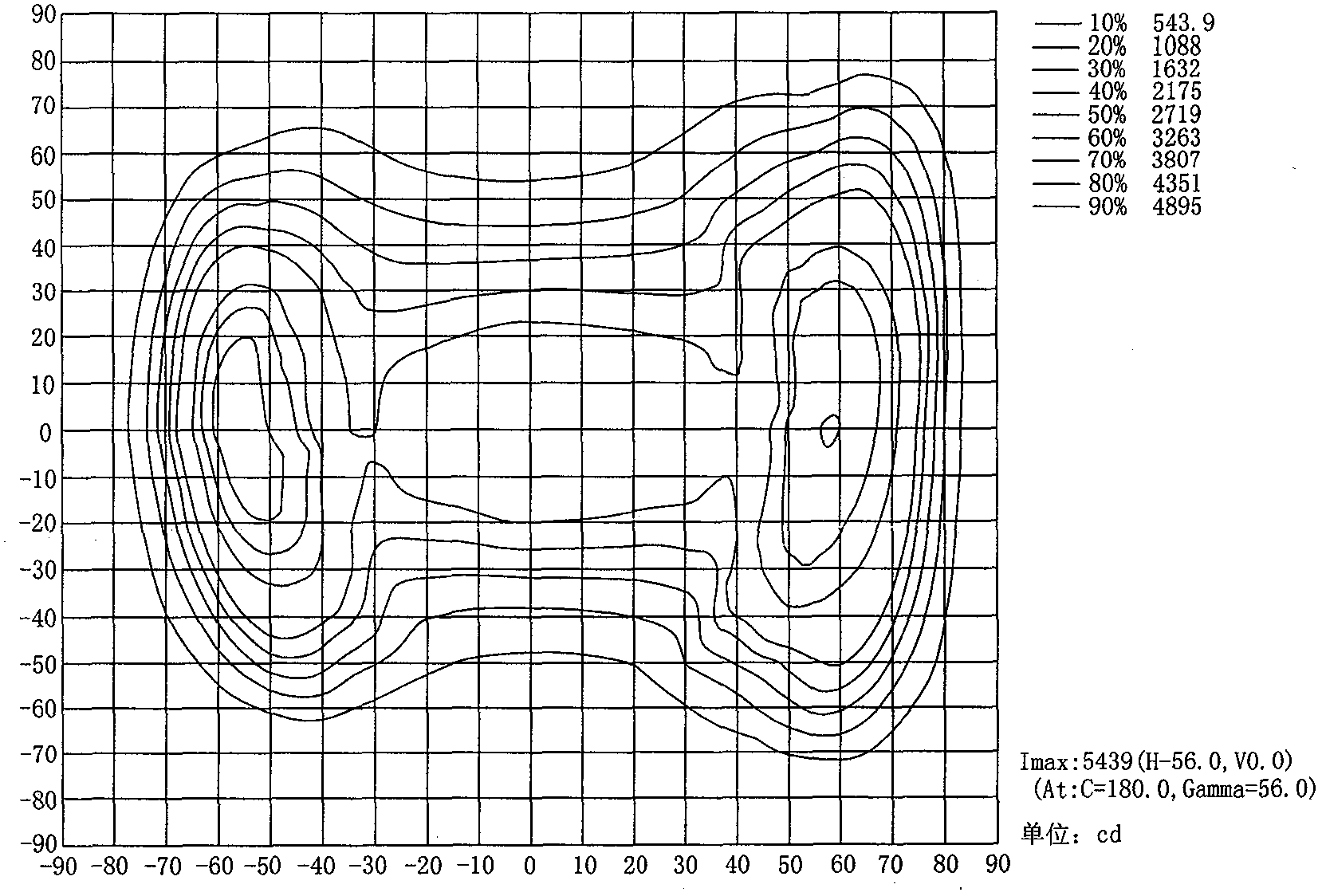
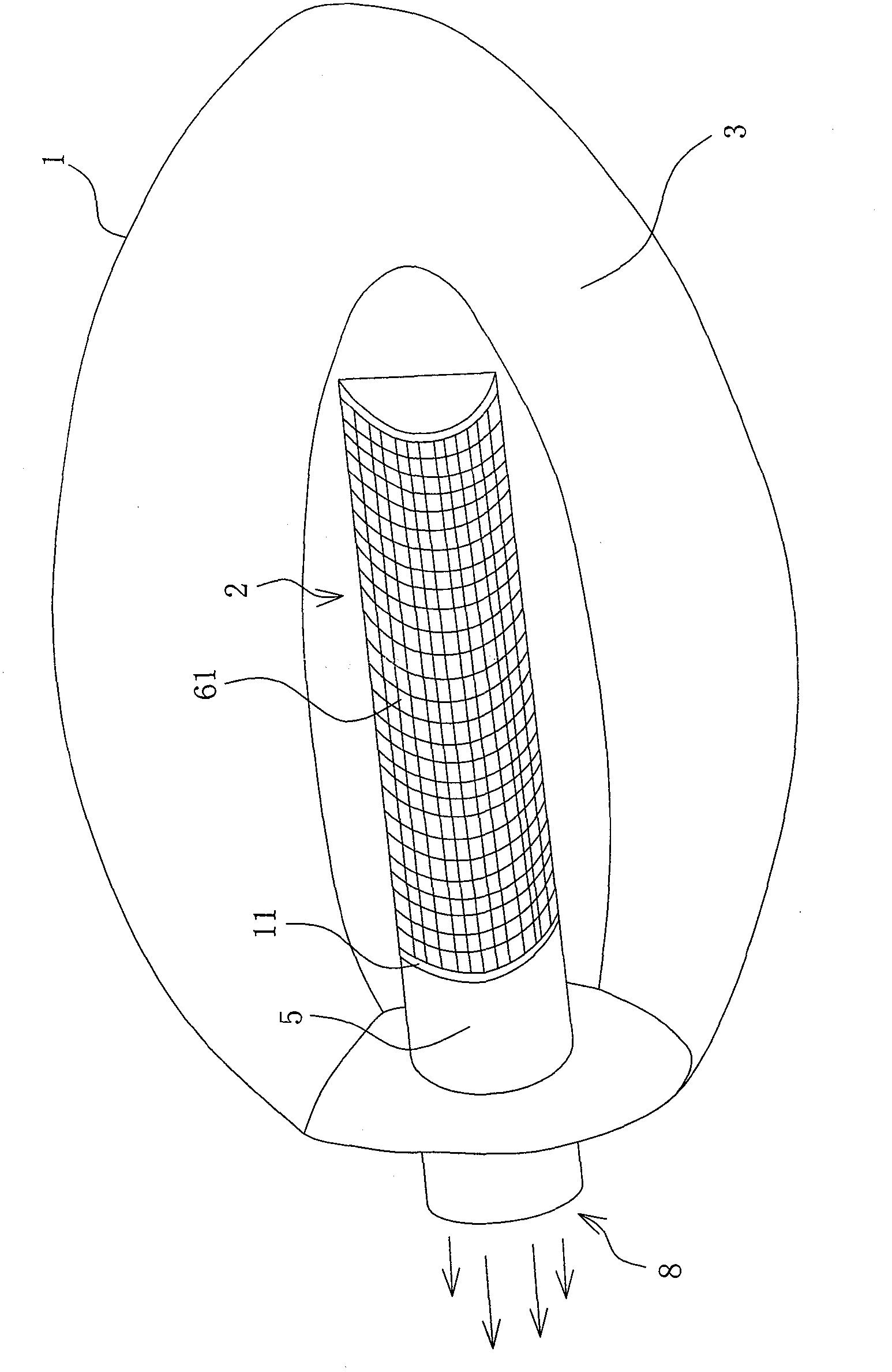
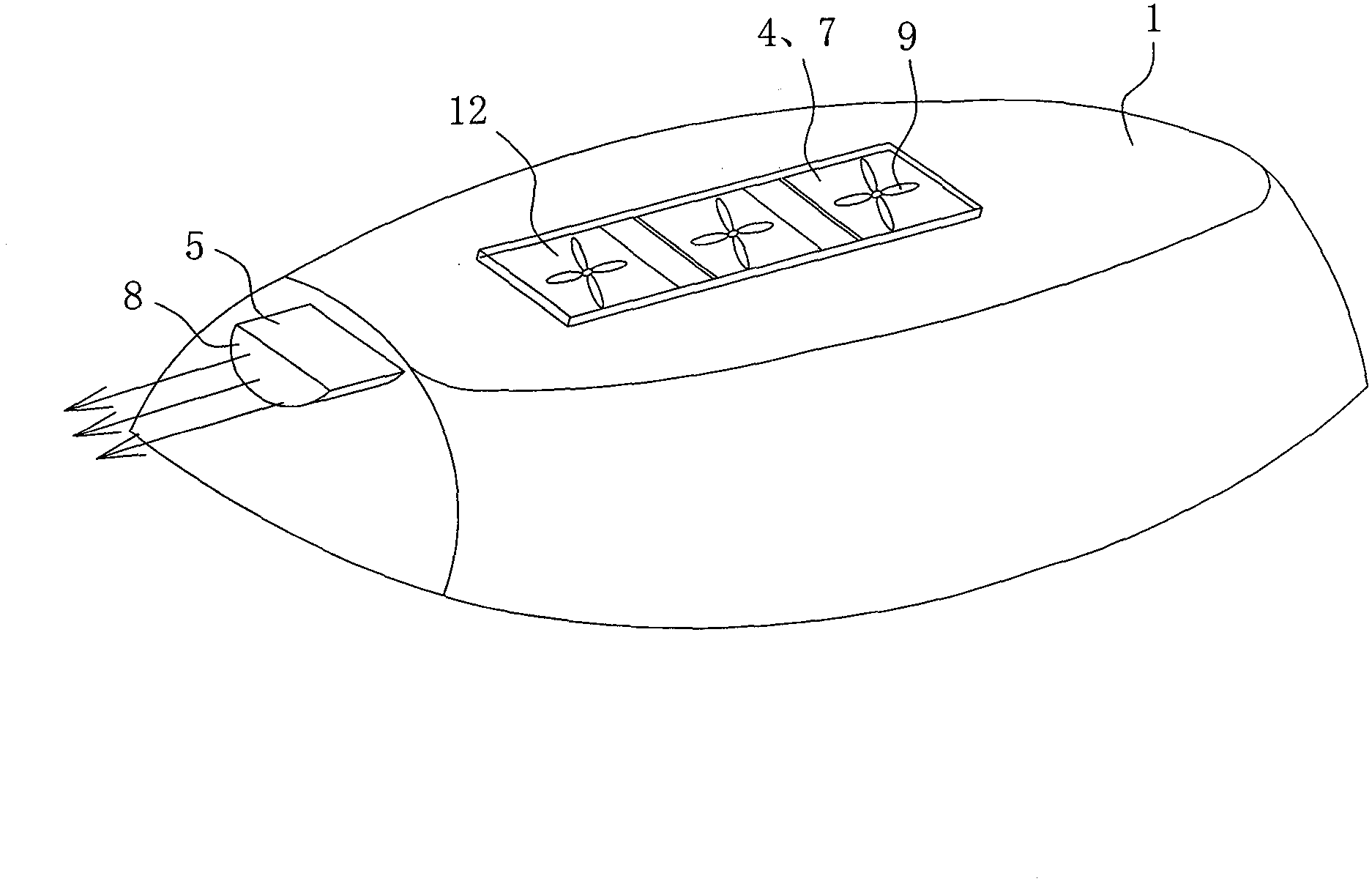
[0024] The optical reflector configured with the LED wick includes a lampshade 1 and the LED wick 2, and the LED wick 2 is installed through a mold on the top of the lampshade inner cavity 3, and the LED wick 2 is a hollow and everted structure. The top of the inner cavity 3 is integrally formed with a light-emitting diode wick support 5 corresponding to the heat dissipation window 4, and the Figure 4 The expressed planar light-emitting diode array module 6 is bent along the shape of the wick holder 5 to form a hollow light-emitting diode wick 2 (such as figure 1 As shown), the wick bracket 5 is also a cooling device bracket. The back of the hollow and everted light-emitting diode wick 2 is an opening structure. The corresponding position is provided with a heat dissipation window 4 communicating with the outside world, the end of the light-emitting diode wick 2 is ...


PUM


Abstract

The invention discloses a manufacturing method of an optical reflector with a luminous diode lampwick and with excellent light distribution effect, good illumination effect consistence and low production cost. The manufacturing method comprises the steps of (1) machining a heat radiation window on the top of a lampshade by utilizing a mold; (2) well clipping a substrate, and inserting a luminous diode on the substrate; (3) welding the luminous diode with the substrate by utilizing dip soldering process; (4) bending the substrate to make the substrate form a hollow upturned structure, and (5) fixedly installing a hollow upturned luminous diode lampwick on the top of an inner cavity of the lampshade by utilizing a mold, making an opening of the luminous diode lampwick be right opposite to the heat radiation window, stretching the outlet of the luminous diode lampwick out of the lampshade, and installing a heat radiation fan on the heat radiation window after the step (5) is completed.

Description

Technical field: [0001] The invention relates to the field of light source technology, in particular to an integrated optical reflector capable of using various light-emitting diodes with different powers to form a high-density wick as a light source and a manufacturing method thereof. Background technique: [0002] Lamps made of high-intensity strong-light wicks through specific optical reflectors can be widely used in searchlights, motor vehicle headlights, and night lighting of streets, roads, bridges or squares, construction sites, etc.; currently, when making these lamps , metal halide wicks or high-pressure sodium wicks are mostly used as light sources. The power dissipation of these lamps is generally about 100-1000 watts. Lamps with metal halide wicks or high-pressure sodium wicks as light sources have the characteristics of good light intensity, mature production technology and low cost. Strong, especially when used as street lighting, its light source and light di...

Claims


Application Information

Patent Timeline
Patent Type & Authority Applications(China)
IPC IPC(8): F21V7/00F21V19/00F21V29/02F21Y101/02F21V29/506F21V29/67F21Y101/00F21Y115/10
Inventor 梁允生
Owner 程小玲
Learn More