Distributing equipment, combined distributing equipment and distributing method thereof

A fabric and equipment technology, applied in lighting and heating equipment, furnace components, furnaces, etc., can solve problems such as failure shutdown of the distribution system, single feeding link, system paralysis, etc., and achieve the effect of avoiding failure shutdown

Inactive Publication Date: 2012-09-19
YUNNAN JIANSHUI MANGANESE
View PDF9 Cites 7 Cited by
  • Summary
  • Abstract
  • Description
  • Claims
  • Application Information

AI Technical Summary

Problems solved by technology

[0003] The current structure of the system has the following deficiencies: 1. The flow cannot be adjusted
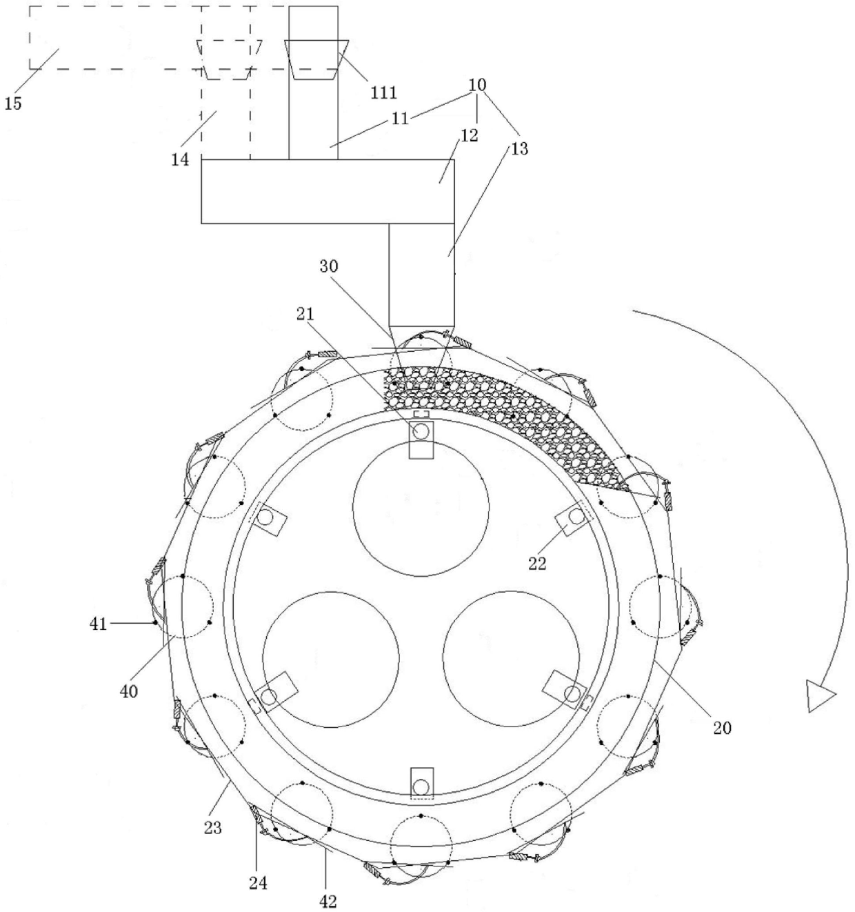
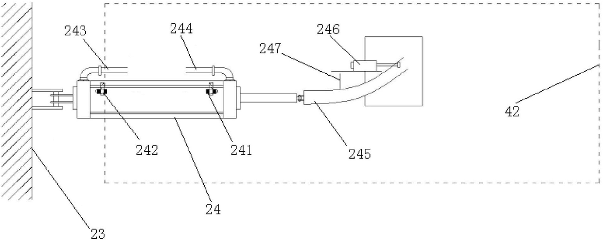
In this way, a problem arises. When the material flow rate is too large, the amount of material stored on the circular material tray increases, and the scraper to be retracted cannot be retracted, causing the entire material distribution system to fail and stop; 2. The feeding link is single , there is a problem in the upper batching link of the system, and when the material cannot be added to the buffer bin immediately, it will affect the entire production; 3. The reliability of the system is not high, and its pneumatic rod such as figure 2 shown
Magnetic proximity switches are used in the raised and retracted positions. Due to the high metal content in the dust during the ferroalloy smelting process, the magnetic proximity switches will fail after a long time, which will cause the entire system to fail.

Method used


Image

  • Distributing equipment, combined distributing equipment and distributing method thereof
  • Distributing equipment, combined distributing equipment and distributing method thereof
  • Distributing equipment, combined distributing equipment and distributing method thereof

Examples


Embodiment Construction

[0021] Embodiments of the present invention are described in detail below, examples of which are shown in the drawings, wherein the same or similar reference numerals designate the same or similar elements or elements having the same or similar functions throughout. The embodiments described below by referring to the figures are exemplary only for explaining the present invention and should not be construed as limiting the present invention.

[0022] In describing the present invention, it should be understood that the terms "center", "longitudinal", "transverse", "upper", "lower", "front", "rear", "left", "right", " The orientations or positional relationships indicated by "vertical", "horizontal", "top", "bottom", "inner", "outer", etc. are based on the orientation or positional relationships shown in the drawings, and are only for the convenience of describing the present invention and simplifying Describes, but does not indicate or imply that the device or element referred...


PUM


Abstract

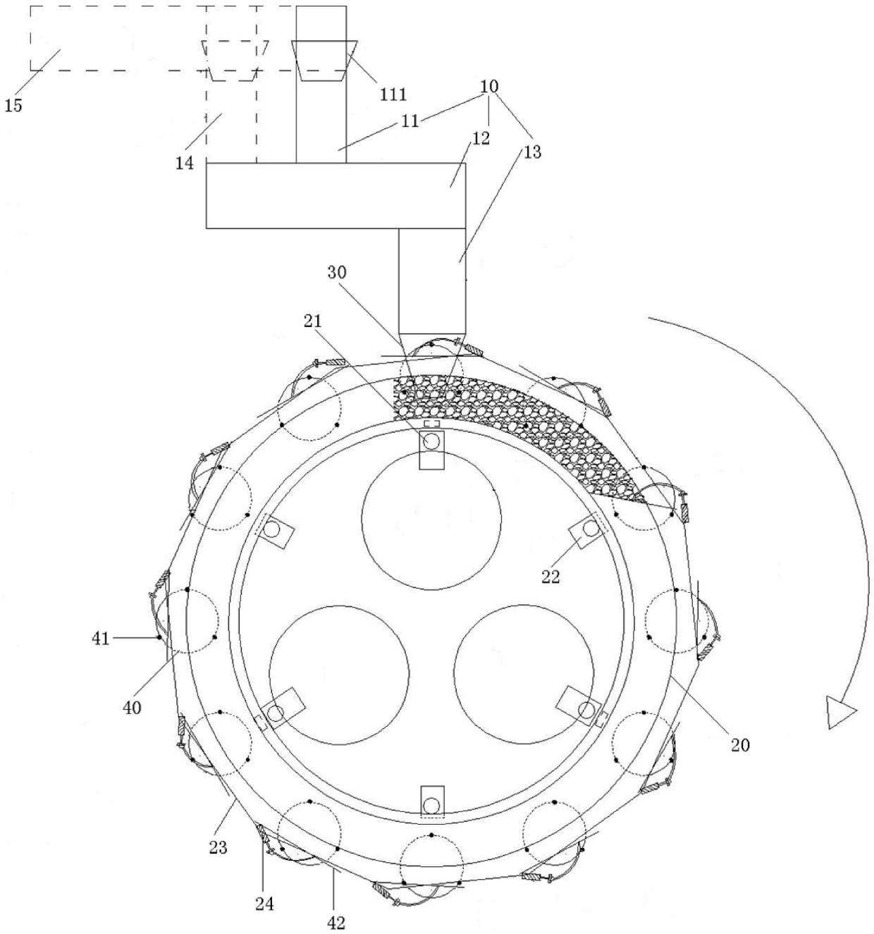
The invention discloses distributing equipment, combined distributing equipment and distributing method thereof. The distributing equipment includes a transmitting device, a tray, a hopper and a bunker, wherein the transmitting device includes first, second and third conveyer belts and first, second and third driving motors driving the first, the second and the third conveyer belts respectively; the first conveyer belt receives materials and transmits the materials to the hopper through the second and the third conveyer belts; the first conveyer belt can positively or reversely transmit the materials; and the first driving motor is a variable frequency motor. According to the distributing equipment of the embodiment provided by the invention, as the first conveyer belt can positively or reversely transmit the materials, and the first driving motor is the variable frequency motor, the flow velocity of the materials can be adjusted according to the particle sizes of the materials, the problem that the feeding flow rate can't be adjusted is solved, and therefore the failure shut-down of the whole distributing system caused by overlarge material flow rate is avoided.

Description

technical field [0001] The invention relates to the field of metallurgy, in particular to a material distribution device, a combined material distribution device and a material distribution method. Background technique [0002] The annular material distribution system is mainly used for arranging certain flow, small particle size and powdery materials. At present, the composition of the system is mainly composed of multiple feeding belts, hoppers, circular material trays, cloth motors, auxiliary drive rollers, pneumatic scrapers, pneumatic rods and PLC control systems. [0003] The current structure of the system has the following deficiencies: 1. The flow cannot be adjusted. Because it adopts the direct transmission mode of the motor gearbox. The flow rate of the material depends on the speed ratio of the gearbox, and it runs at a constant speed. Because the working principle of the system is that the load cell detects that the material level of certain silos is lower th...

Claims


Application Information

Patent Timeline
Patent Type & Authority Applications(China)
IPC IPC(8): F27D3/00
Inventor 杭祖辉何涛王璠张志斌
Owner YUNNAN JIANSHUI MANGANESE
Why Eureka
Try Eureka