Light-receiving module for light-emitting element and inspection device for light-emitting element

A technology for light-emitting elements and receiving modules, which is applied in the field of inspection devices for light-emitting elements, and can solve problems such as calculating the amount of light

Inactive Publication Date: 2012-09-19
PIONEER CORP +1
View PDF7 Cites 4 Cited by
  • Summary
  • Abstract
  • Description
  • Claims
  • Application Information

AI Technical Summary

Problems solved by technology

[0006] However, the method described in Patent Document 1 can only measure the amount of light within the range of ±10° from the emitting angle of the LED, and it is difficult to accurately calculate the am

Method used


Image

  • Light-receiving module for light-emitting element and inspection device for light-emitting element
  • Light-receiving module for light-emitting element and inspection device for light-emitting element
  • Light-receiving module for light-emitting element and inspection device for light-emitting element

Examples


Embodiment Construction

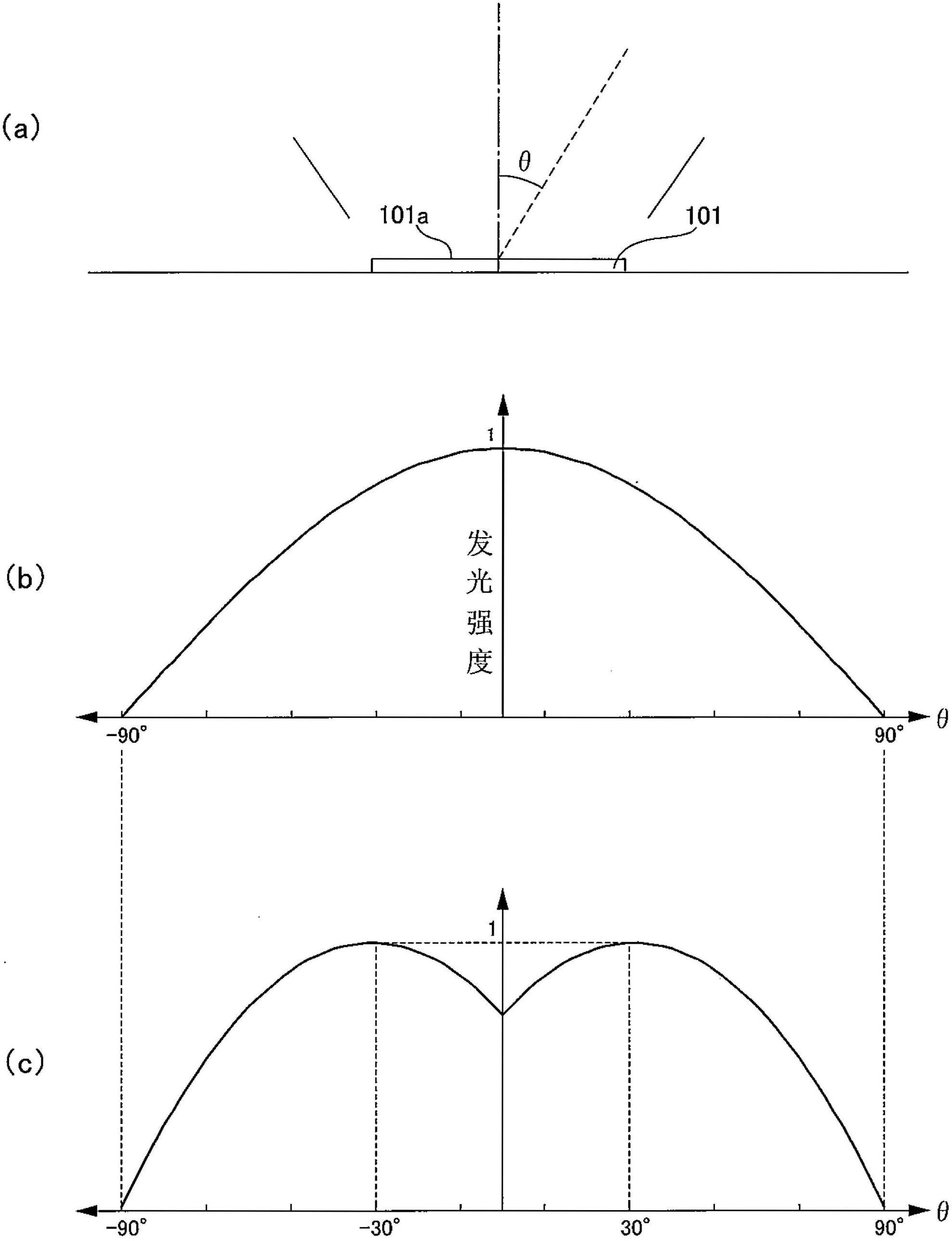
[0025] Below, use figure 1 The first embodiment of the present invention will be described in detail. figure 1 It is explanatory drawing of the light emission state of LED101 in 1st Embodiment of this invention.

[0026] Such as figure 1 As described in (a), LED101 emits light from the light emitting surface 101a.

[0027] Here, LED101 is an example of a light emitting element, and other light emitting elements can also be used similarly.

[0028] In addition, θ is an angle formed with the normal direction of the light emitting surface 101a.

[0029] The LED 101 emits light for every angle θ.

[0030] figure 1 (b) and figure 1 (c) is a light quantity distribution diagram of LED101 at angle (theta).

[0031] figure 1 (b) is an example of LED101 (cos type) whose light intensity is the strongest when θ is 0°, figure 1 (c) is an example of LED 101 (ring type) where light intensity is strongest when θ is around 30°.

[0032] However, some manufacturing errors exist when m...


PUM


Abstract

The purpose of the present invention is to provide a light-receiving module for a light-emitting element and a detection device for the light-emitting element, that are capable of precisely calculating the amount of light emitted by the light-emitting element. The light-receiving module (1) for the light-emitting element has: a photodetector (105) arranged to face an LED (101), that receives light emitted by the LED (101) and measures the amount of said light; and a light guide section (104) that guides light emitted by the LED (101) to a wavelength measurement unit (121) for measuring the wavelength of light emitted by the LED (101). The light guide section (104) is arranged to extend into the space formed by a flat surface formed by the LED (101) surface that faces the photodetector (105) and a flat surface formed by the photodetector (105) surface that faces the LED (101), and is formed so that the extension direction of the light guide section (104) does not match the optical axis from the LED (101).

Description


Claims


Application Information

Patent Timeline
Owner PIONEER CORP
Why Eureka
Try Eureka