Rotary drilling rig and pulley yoke thereof

A technology of rotary drilling rig and pulley frame, which is applied in the direction of rotary drilling rig, rotary drilling, drill pipe, etc., which can solve the problems of mast interference, poor versatility, and inability to realize multi-functional drilling rigs, so as to avoid interference and increase The scope of application and the effect of increasing the lifting range

Inactive Publication Date: 2012-09-26
BEIJING SANY HEAVY MASCH CO LTD
View PDF6 Cites 8 Cited by
  • Summary
  • Abstract
  • Description
  • Claims
  • Application Information

AI Technical Summary

Problems solved by technology

[0005] The two large pulley assemblies of the existing pulley frame (hanging anchor frame) are rigidly connected through the pulley frame body, and can only be equipped with drilling tools of one construction method, which cannot realize the multi-function of the drilling rig. It is replaced with CFA (Continuous Flight Auger) , that is, continuous drilling with auger drilling tools and grouting construction method) and other construction methods need to replace the pulley frame, and the versatility is not good
The two small pulley assemblies are rigidly connected by a pulley frame, and the distance between the lifting center and the mast is fixed. When lifting a heavy object with a large outer diameter, it is easy to interfere with the mast

Method used


Image

  • Rotary drilling rig and pulley yoke thereof
  • Rotary drilling rig and pulley yoke thereof
  • Rotary drilling rig and pulley yoke thereof

Examples


Embodiment 1

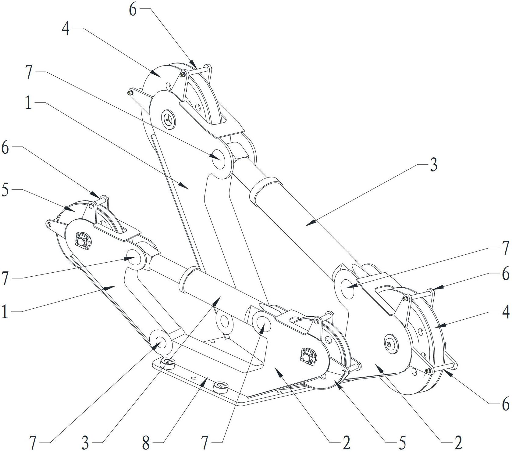
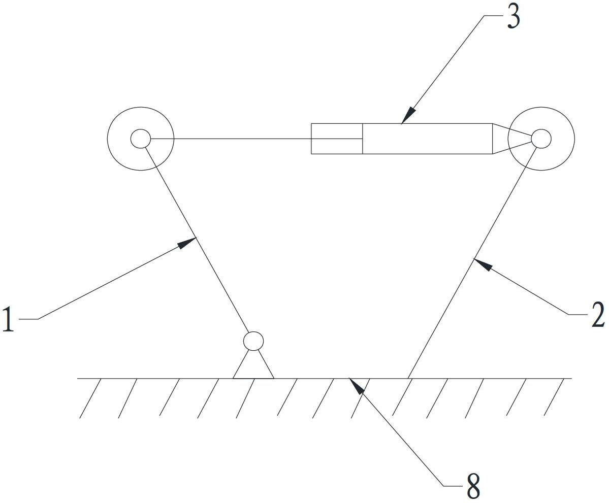
[0035] figure 1 and figure 2Is the relevant drawings of this embodiment, as shown in the figure, the device is a pulley frame for a rotary drilling rig, which includes a base 8 installed on the top of the mast of the rotary drilling rig and a first base mounted on the base 8 A pulley assembly and a second pulley assembly. In practical applications, generally speaking, the first pulley assembly is a large pulley assembly with a larger pulley diameter, and the second pulley assembly is a small pulley assembly with a smaller pulley diameter. The large pulley assembly Cooperate with the main hoisting wire rope, the small pulley assembly is matched with the auxiliary hoisting wire rope, and one side of the base 8 is rotatably connected with the top of the mast. In this embodiment, the rotatable connection mainly refers to but is not limited to the hinged form , the other three sides can be fixedly connected to the top of the mast with bolts, so that when the mast is down, the bol...

Embodiment 2

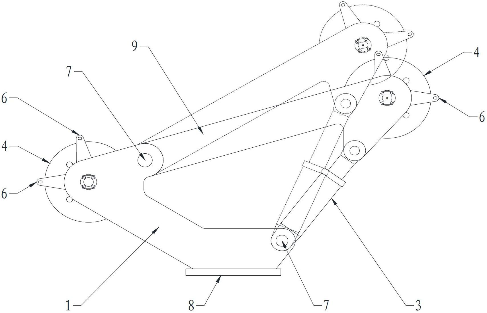
[0038] image 3 and Figure 4 It is the related drawings of this embodiment, as shown in the figure, compared with Embodiment 1, in this embodiment, the lower end of the forearm 1 is fixedly connected with the base 8, and the upper end is hinged with a non-stretchable cross arm 9, and the The rear arm is set as a telescopic hydraulic cylinder 3, the cylinder body of the hydraulic cylinder 3 is hinged to the base 8, and the piston rod is hinged to the other end of the cross arm 9. In addition, the structure and function of this embodiment are consistent with the first embodiment , so it will not be repeated here.

[0039] Similarly, as other modified implementations of this embodiment, the base may not be provided, and the large pulley assembly and the small pulley assembly may be directly connected to the top of the mast; only one of the two pulley assemblies may use a hydraulic cylinder to adjust the distance between the two pulleys. Distance, another pulley assembly that u...

Embodiment 3

[0041] Figure 5 That is the relevant drawings of this embodiment, as shown in the figure, compared with Embodiment 2, in this embodiment, both the forearm and the rear arm are set as hydraulic cylinder 3, and both ends of hydraulic cylinder 3 are also It is connected to the cross arm 9 and the base 8 in a hinged manner. Except for this, the structure and function of this embodiment are consistent with the second embodiment, so no more details are given.

[0042] Similarly, as other modified implementations of this embodiment, the base 8 may not be provided, and the large pulley assembly and the small pulley assembly may be directly connected to the top of the mast; only one of the two pulley assemblies may use the hydraulic cylinder 3 to adjust the two pulleys. The distance between, another pulley assembly that uses the existing non-adjustable pulley distance; the front arm and cross arm can be set as hydraulic cylinder 3, or the rear arm and cross arm can be set as hydraulic...


PUM


Abstract

The invention provides a rotary drilling rig and a pulley yoke thereof. The pulley yoke is mounted on at least one pulley assembly on the top of a mast of the rotary drilling rig. The pulley assembly is matched with a winding wire rope of the rotary drilling rig. The pulley assembly comprises a front arm disposed on the top of the mast, a rear arm, a transverse arm and pulleys disposed on the front arm and the rear arm respectively. Two ends of the transverse arm are connected with the front arm and the rear arm respectively. At least one of the front arm, the rear arm and the transverse arm is telescopic so as to adjust distance between the pulley on the front arm and the pulley on the rear arm. By the pulley yoke, work range of a main pulley is increased, work range of the rotary drilling rig is increased, multi-functionality of the rotary drilling rig is achieved, auxiliary hoisting range is expanded, and intervention of hosting objects with the mast is avoided.

Description

technical field [0001] The invention relates to the field of engineering machinery, in particular to a rotary drilling rig and a pulley frame thereof. Background technique [0002] With the development of my country's economy, rotary drilling rigs are more and more widely used in pile hole construction. The construction of modern piling foundations is becoming more and more detailed, with more and more types, and there are more and more requirements for the construction range of rotary drilling drills. The demand for a fast and efficient multifunctional rotary drilling rig that can quickly adapt to different construction methods and different hole diameters is increasing. [0003] A typical rotary drilling rig includes a traveling mechanism. The mast and various control devices of the rotary drilling rig are fixed on the chassis of the traveling mechanism. The drill pipe is installed at the end of the mast through a hoisting device. The movement of the rod, the power head ...

Claims


Application Information

Patent Timeline
Patent Type & Authority Applications(China)
IPC IPC(8): E21B19/02E21B15/00E21B3/00
Inventor 肖冰
Owner BEIJING SANY HEAVY MASCH CO LTD
Why Eureka
Try Eureka