Cavity forming apparatus for embedded chamber of underground engineering test model

A test model and underground engineering technology, applied in underground chambers, mining equipment, earthwork drilling, etc., can solve the problem of inability to bury the chamber into a cavity, and achieve a simple structure, easy extraction and molding, and low price. Effect

Active Publication Date: 2012-09-26
SHANDONG UNIV
View PDF2 Cites 8 Cited by
  • Summary
  • Abstract
  • Description
  • Claims
  • Application Information

AI Technical Summary

Problems solved by technology

This mold can only be used for the study of plane strain problems and cannot be used for cavity formation of buried cavities

Method used


Image

  • Cavity forming apparatus for embedded chamber of underground engineering test model
  • Cavity forming apparatus for embedded chamber of underground engineering test model
  • Cavity forming apparatus for embedded chamber of underground engineering test model

Examples


Embodiment Construction

[0036] The present invention will be further described below in conjunction with the accompanying drawings and embodiments.

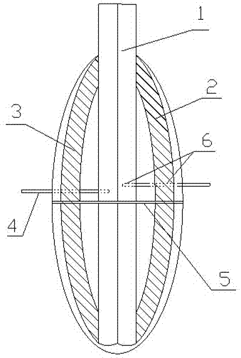
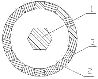
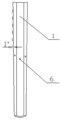
[0037] Such as Figure 1-9 As shown, the central mandrel 1 is provided with 18 positioning pin holes 6, and the central mandrel 1 forms an ellipsoid cavity structure with the surrounding A-shaped arcuate block 2 and B-shaped arcuate block 3, and the arcuate block includes There are 18 pieces in total of A-type arcuate block 2 and B-type arcuate block 3, which surround the center axis 1 in the order of ABA. Each arcuate block is provided with a positioning pin hole 6 and is fixed on the central mandrel 1 through a positioning pin rod 4 . A size-adjustable hoop 5 is arranged at the largest section in the middle of the outside of the ellipsoid cavity structure to tighten all the blocks.

[0038] The central axis 1 is in the form of an inverted hexagonal truncated pyramid, and its bottom surface is a partial ellipsoid, and the angle between each cone surf...


PUM


Abstract

The invention relates to a cavity forming apparatus for an embedded chamber of underground engineering test model, comprising a middle mandrel and arched block bodies. The matching arched block bodies are arranged outside the middle mandrel through positioners and compose an ellipsoid cavity structure together. When in use, the cavity forming apparatus is firstly fixed on a designed position, and pin rods and a hoop are removed when model materials are filled to a corresponding position of the apparatus layer by layer. When the materials are filled to a cavity opening layer by layer, the middle mandrel is removed, then an arbitrary B type arched block body is removed so the other block bodies all can be removed, and thus the embedded chamber is formed inside the model. The apparatus of the invention solves the technical problem that the embedded chamber cannot be formed through excavation, and is simple in structure, low in cost, easy in assembling, and convenient in dismounting, and can be used repeatedly.

Description

[0001] technical field [0002] The invention relates to a cavity-forming device, in particular to a cavity-forming device for embedding caverns in deep underground engineering test models in the fields of energy, resources and national defense engineering. Background technique [0003] In recent years, with the continuous development of the national economy and the implementation of the western development strategy, the development of large-scale projects such as water conservancy, hydropower, energy, transportation, and national defense has become the focus of my country's economic construction. Many large-scale water conservancy and hydropower projects, energy projects, transportation projects and national defense projects are being gradually constructed. These large-scale engineering construction projects involve many problems related to rock mass strength failure, deformation instability and reinforcement treatment. For these complex problems, on the one hand, theoreti...

Claims


Application Information

Patent Timeline
Patent Type & Authority Applications(China)
IPC IPC(8): E21D13/04
Inventor 张强勇李术才段抗贾超刘健蔡兵许孝滨曹冠华
Owner SHANDONG UNIV
Why Eureka
Try Eureka