

Pressure sensor
A pressure sensor, sensor chip technology, applied in the direction of measuring fluid pressure, instruments, fluid pressure measurement by changing ohmic resistance, etc., can solve the problem of sensor output characteristic changes, changes, etc.
- Summary
- Abstract
- Description
- Claims
- Application Information
AI Technical Summary
Problems solved by technology
Method used
Image

Examples
no. 1 example
[0030] The pressure sensor 10 of this embodiment can be used to measure, for example, the pressure of a corrosive pressure medium such as a corrosive liquid or gas. Specifically, the pressure sensor 10 may be used to measure exhaust gas pressure in an exhaust pipe of a diesel vehicle. Alternatively, the pressure sensor 10 can be used to measure the pressure difference before and after an exhaust gas purification filter (such as a diesel particulate filter) in the exhaust pipe. Alternatively, pressure sensor 10 may be used to measure pressure in an exhaust gas recirculation (EGR) system.
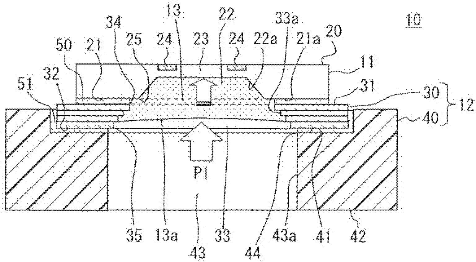
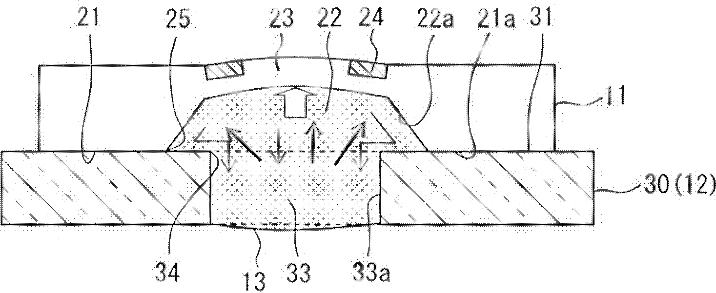
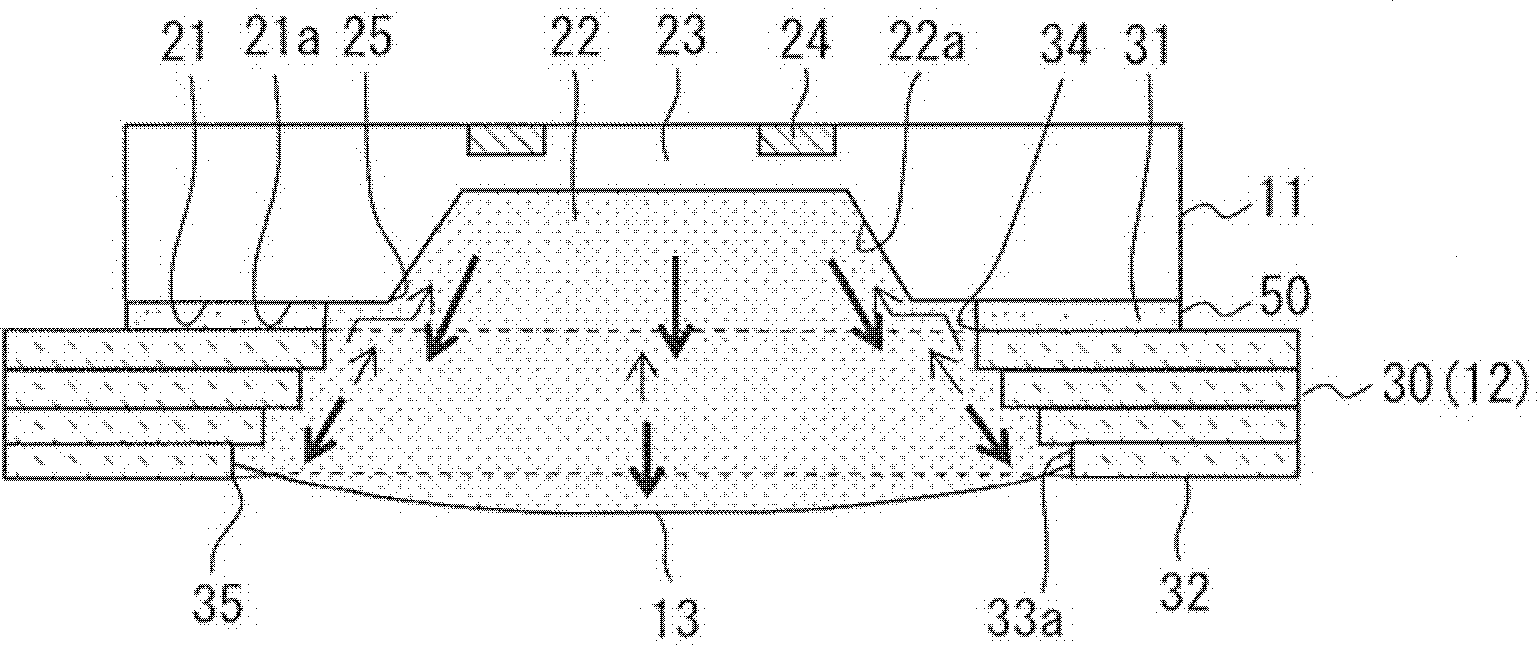
[0031] Such as figure 1 As shown, the pressure sensor 10 includes a sensor chip 11 , a support member 12 , a gel member 13 and an adhesive layer 50 . The sensor chip 11 has a concave portion 22 . The support member 12 supports the sensor chip 11 and defines through-holes 33 , 43 serving as pressure transmission channels. At least a part of the concave portion 22 and the through holes 33 ,...
no. 2 example
[0084] In the first embodiment, the gel member 13 continuously fills the area of the through hole 33 extending from the concave portion 22 to the stem. In contrast, in the second embodiment, as Figure 11 As shown, the gel member 13 continuously fills the area extending from the recessed portion 22 to the through hole 43 of the case 40 . A third inner edge 44 surrounding the open end of the through hole 43 on the stem mounting surface 41 of the case 40 faces the rear surface 32 of the stem 30 . Except for the area filled with gel member 13, such as Figure 11 The pressure sensor 10 shown has a substantially figure 1 The pressure sensor 10 of the first embodiment shown has the same structure. In view of this, in this embodiment, the third inner edge 44 is arranged radially outwards compared to the fourth inner edge 35 which surrounds the opening of the through hole 33 on the rear surface 32 of the stem 30 end. exist Figure 11 In , the gel member 13 is in a deformed sta...
no. 3 example
[0094] In the above-described embodiment, at room temperature, the surface of the gel member 13 has a meniscus shape such that the surface is concave in a direction away from the diaphragm 23 (see figure 1 ). On the contrary, in the third embodiment, as Figure 13 As shown, at room temperature, the surface of the gel member 13 has a meniscus shape such that the surface is convex in a direction away from the diaphragm 23 . In addition to the surface shape of the gel member 13, such as Figure 13 The pressure sensor 10 shown can have the same characteristics as the pressure sensor 10 of the first embodiment (eg figure 1 shown) have substantially the same structure.
[0095] When the surface of the gel member 13 has a meniscus shape and is convex in a direction away from the diaphragm 23, compared with when the gel member 13 is flat or concave in a direction away from the diaphragm 23, the gel member can be along the It is easier to move in a direction away from the diaphragm...
PUM
 Abstract
Description
Claims
Application Information