Fault diagnosis method of blast furnace top gearbox through comprehensive analysis
A technology for fault diagnosis and comprehensive analysis, which is applied in the analysis of materials, the use of sonic/ultrasonic/infrasonic waves to analyze solids, thermometer components, etc., to achieve the effects of predictive maintenance, accurate measurement results, and improved data transmission efficiency
- Summary
- Abstract
- Description
- Claims
- Application Information
AI Technical Summary
Problems solved by technology
Method used
Image

Examples
Embodiment Construction
[0036] The present invention will be described in detail below in conjunction with the accompanying drawings.
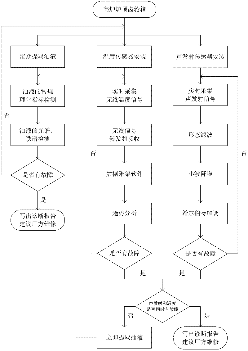
[0037] Such as figure 1 As shown, a comprehensive application of acoustic emission signal analysis, wireless temperature measurement analysis and oil analysis for 2000m 3 The process of the fault diagnosis method for the blast furnace top gear box without material bell is as follows: using acoustic emission detection technology, wireless temperature measurement technology and oil liquid detection technology for the blast furnace top gear box respectively, and then combining the results of the three to carry out the final fault diagnosis.
[0038] Such as figure 2 As shown, there are four main steps in the analysis of acoustic emission signals:
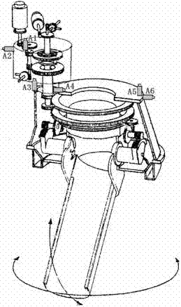
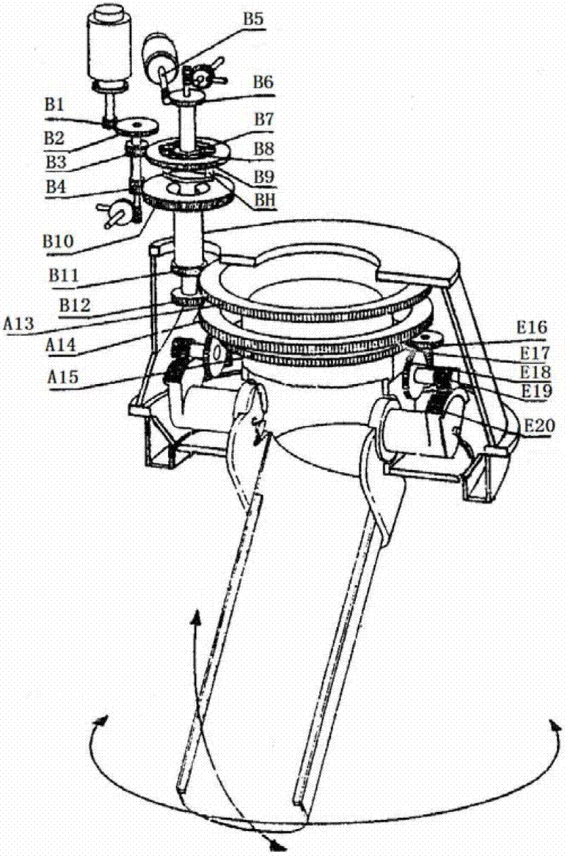
[0039] 1) image 3 It is a structural schematic diagram of the top gear box of the blast furnace, and B1-E20 is the gear number of the blast furnace transmission system. Figure 4Is the installation diagram of the acoust...
PUM
 Abstract
Description
Claims
Application Information
PatSnap Eureka turns technology decisions into work you can execute. Powered by our Innovation Knowledge Graph, it runs expert workflows across engineering, life sciences, materials and intellectual property. Get your review-ready output in minutes.


