Semi-automatic error correction braking system with inward rotating solenoid valve having fixed rotation angle

A braking system and solenoid valve technology, applied in the field of error correction braking system, can solve the problems of complex structure, low practicability, and many microelectronic devices.

Active Publication Date: 2012-10-03
江苏富莱士机械有限公司
View PDF8 Cites 2 Cited by
  • Summary
  • Abstract
  • Description
  • Claims
  • Application Information

AI Technical Summary

Problems solved by technology

One of the disadvantages of this technology is that the practicability of the mechanical device for starting the car brake is not strong
[0003] Chinese patent application 201001130092.4 "A Device for Automatically Correcting Misstepped Accelerators into Brakes with the Coordination of Electric Appliances and Machinery" discloses a device including a sensor, a signal analyzer and a brake activation mechanism. There are many electronic devices, and the reliability is reduced; the second disadvantage is that in the brake activation mechanism, the circular motion of the solenoid valve is changed into the reciprocat

Method used


Image

  • Semi-automatic error correction braking system with inward rotating solenoid valve having fixed rotation angle
  • Semi-automatic error correction braking system with inward rotating solenoid valve having fixed rotation angle
  • Semi-automatic error correction braking system with inward rotating solenoid valve having fixed rotation angle

Examples


Embodiment 1

[0046] Embodiment 1. Semi-automatic error correction braking system for internally rotating fixed angle solenoid valve

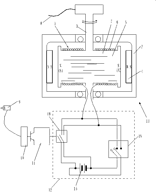
[0047] Such as figure 1 , 2 , 3, including the sensor 9---sensing signal analyzer 10---control signal power amplifier 11---power controller 12 connected successively in order to transmit electrical signals, and in order to convert electrical energy into mechanical energy, use The power controller 12 is connected with the solenoid valve 14 whose inner fork-shaped rotating body is a fixed angle of rotation, and the power controller 12 is connected with the DC power supply 15 that drives the electromagnetic valve 14 whose inner fork-shaped rotating body is a fixed angle of rotation.

[0048] The following is a description of each part:

[0049] The sensor 9 is one of a pressure sensor, a speed sensor or an acceleration sensor or a combination thereof; the sensor 9 transmits a sensing signal to a sensing signal analyzer 10 . That is to say, sensor 9 is to use...

Embodiment 2

[0059] Embodiment 2, semi-automatic error correction braking system of internal rotation fixed angle solenoid valve

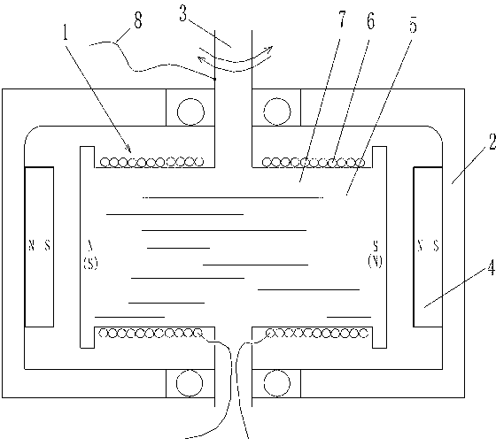
[0060] As in embodiment 1, after the two coils 6 wound in the same direction are penetrated respectively from the two ends of a straight iron core 7, a coil larger than the straight iron core 7 is respectively fixed at the two ends of the straight iron core 7. Core 7 cross-sections, the gear coil block identical with straight iron core 7 materials, make this straight iron core 7 become " I " font. Also carry out the same process to another straight iron core 7, also become " I " font straight iron core 7.

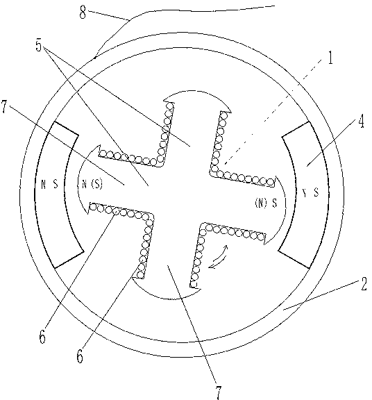
[0061] The outer surface of the rotating shaft 3 of the inner fork-shaped rotating body 1 is fixedly connected with one end of a stay cord 8, and the other end of the stay cord 8 is connected with the driven object. When the inner fork-shaped rotating body 1 is rotated at an angle of 80 degrees, the stay cord 8 is pulled at an angle of 80 degrees correspond...

Embodiment 3

[0062] Embodiment 3, semi-automatic error correction braking system of internal rotation fixed angle solenoid valve

[0063] As embodiment 1, but only the inner fork-shaped rotating body is the minimum included angle of the "cross" shaped piece of the solenoid valve 14 of fixed rotation angle and changes it into 10 degrees.


PUM


Abstract

The invention relates to a semi-automatic error correction braking system with an inward rotating solenoid valve having fixed rotation angle, in particular to the semi-automatic error correction braking system which can change an accidental step on an accelerator into an error correction braking. The semi-automatic error correction braking system comprises a sensor, a sensor signal analyzer, a control signal amplifier and a power supply controller, which are sequentially connected with one another. The power supply controller is connected with the solenoid valve with an inner fork-shaped rotator and a direct current power supply which drives the solenoid valve with the inner fork-shaped rotator. The semi-automatic error correction braking system with the inward rotating solenoid valve having fixed rotation angle has the advantages that response speed from detecting the accidental step on the accelerator to correcting the accidental step into braking is fast, the solenoid valve which drives a brake is accurate in operation, full-automatic error correction braking can be achieved, no rotator locking occurs, and a braking state can be maintained for a long time without power consumption until a driver manually restores a state before the system starts.

Description

technical field [0001] The invention belongs to the technical field of braking of automobiles, in particular, it can transform the human operation of stepping on the accelerator by mistake into an error-correcting braking system capable of automatic braking. Background technique [0002] Chinese patent 200510022077.X "Accelerator System Device with Annunciator" provides a device that can judge whether the accelerator action is correct or wrong before determining whether to remedy and brake, so that the accelerator can be used for both braking and acceleration. Motor vehicle accelerator pedal system. It is characterized in that an annunciator is arranged on any one of the accelerator pedal, the linkage device and the vehicle body device. The annunciator is connected with the electric valve that can cut off the engine oil circuit and the electric valve on the wheel brake. This technology proposes to use electronic settings to perceive the action of misstepping the accelerato...

Claims


Application Information

Patent Timeline
IPC IPC(8): B60T7/04B60K26/02
Inventor 黄强
Owner 江苏富莱士机械有限公司
Why Eureka
Try Eureka