Dual-redundancy electric brake device of airplane and control method for dual-redundancy electric brake device

A dual-redundancy, electric braking technology, applied in the direction of braking transmissions, brakes, vehicle components, etc., can solve the problems of low reliability, improve life and reliability, and ensure safe braking

Inactive Publication Date: 2012-10-03
NORTHWESTERN POLYTECHNICAL UNIV
View PDF7 Cites 21 Cited by
  • Summary
  • Abstract
  • Description
  • Claims
  • Application Information

AI Technical Summary

Problems solved by technology

None of these electric brakes use redundant technology, and the reliability is not high

Method used


Image

  • Dual-redundancy electric brake device of airplane and control method for dual-redundancy electric brake device
  • Dual-redundancy electric brake device of airplane and control method for dual-redundancy electric brake device
  • Dual-redundancy electric brake device of airplane and control method for dual-redundancy electric brake device

Examples


Embodiment Construction

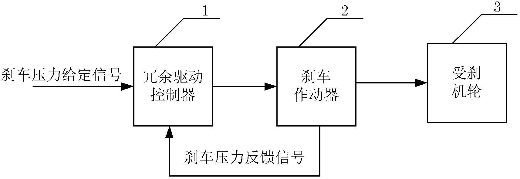
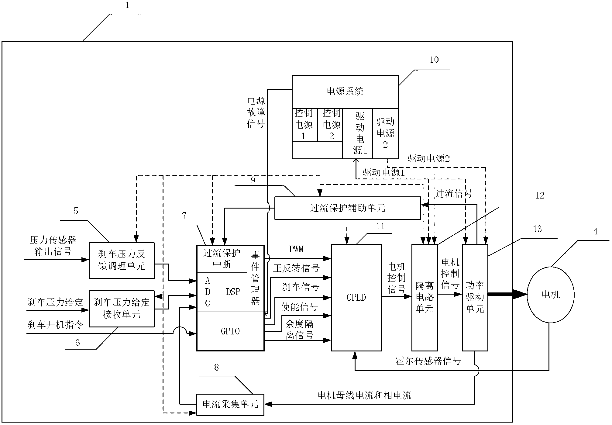
[0027] like figure 1 As shown, the present invention includes a redundant drive controller 1 , a brake actuator 2 and braked wheels 3 . Redundant drive controller 1 receives the braking pressure given signal, and is controlled by the control method to drive the double-redundant brushless DC motor 4 in the braking actuator 2 to work, so that the braking pressure applied to the braked wheel 3 follows the braking Pressure given signal. In the present invention, the control power supply, the driving power supply, the motor winding, the motor Hall sensor, the pressure sensor, and the power drive unit are designed for backup.

[0028] Among them, the redundant drive controller 1 includes a brake pressure feedback conditioning unit 5, a brake pressure given receiving unit 6, a DSP unit 7, a CPLD unit 11, an isolation circuit unit 12, a power drive unit 13, a current acquisition unit 8, an overcurrent protection Auxiliary unit 9 and power system unit 13 . The given brake pressure r...


PUM


Abstract

The invention discloses a dual-redundancy electric brake device of an airplane and a control method for the dual-redundancy electric brake device. A redundant driving controller part receives a brake pressure given signal and drives a brake actuator to work, so that brake pressure applied to a braked wheel follows the brake pressure given signal. By adopting a redundant technology, easily damaged mechanisms in an airplane brake driving device are subjected to warm backup; under the condition of normal working, the corresponding parts work at half of rated power, so that the service life of the driving device is prolonged, and the reliability of the driving device is improved; when certain redundancy of the driving device fails, a fault can be detected in real time and isolated, so that a fault motor quits a working state, and the driving device runs after being switched to a single-channel mode; and therefore, the reliability of a braking system of an airplane is improved.

Description

technical field [0001] The invention relates to a dual-redundancy electric braking device and a control method, in particular to an aircraft dual-redundancy electric braking device and a control method. Background technique [0002] The aircraft braking system is a subsystem with relatively independent functions on the aircraft. Its function is to bear the static weight of the aircraft, dynamic impact load and absorb the kinetic energy of the aircraft when it lands, so as to realize the braking and control of the aircraft's take-off, landing, taxiing, and turning. [0003] At present, the research results of the electric brake control system include: the patent "Aircraft Electric Brake Control System Framework" with the publication number CN101117155 and the patent "Reducing Power Mode of the Aircraft Full Electric Brake System" with the publication number CN101568458, which are two technologies studied by Boeing. . The article "Design and Key Technology Research of Aircraf...

Claims


Application Information

Patent Timeline
Patent Type & Authority Applications(China)
IPC IPC(8): B60T13/74B60T8/17
Inventor 林辉戴志勇苏田青郭皓齐蓉
Owner NORTHWESTERN POLYTECHNICAL UNIV
Why Eureka
Try Eureka