Shear wall with 'profile steel column-steel beam-steel support' embedded between steel tube concrete columns and manufacturing method

A technology of concrete-filled steel tube columns and concrete-filled steel tubes, which is applied to walls, building components, buildings, etc., to achieve the effects of good stability of later bearing capacity, improvement of elastic initial stiffness, and optimization of energy dissipation capacity

Active Publication Date: 2012-10-03
BEIJING UNIV OF TECH
View PDF3 Cites 21 Cited by
  • Summary
  • Abstract
  • Description
  • Claims
  • Application Information

AI Technical Summary

Problems solved by technology

[0005] The technical problem to be solved by the present invention is to significantly improve the bearing capacity, ductility and seismic energy dissipation capacity of the shear wall. The present invention combines the advantages of the composite shear wall with a frame and the composite shear wall with a built-in truss, and provides a A new type of steel-concrete composite shear wall that consumes the energy input from the earthquake and improves the seismic performance of the structure. It is suitable for the seismic design of high-rise buildings and complex multi-storey buildings.

Method used


Image

  • Shear wall with 'profile steel column-steel beam-steel support' embedded between steel tube concrete columns and manufacturing method
  • Shear wall with 'profile steel column-steel beam-steel support' embedded between steel tube concrete columns and manufacturing method
  • Shear wall with 'profile steel column-steel beam-steel support' embedded between steel tube concrete columns and manufacturing method

Examples


Embodiment Construction

[0036] The present invention will be further described below in conjunction with specific embodiment:

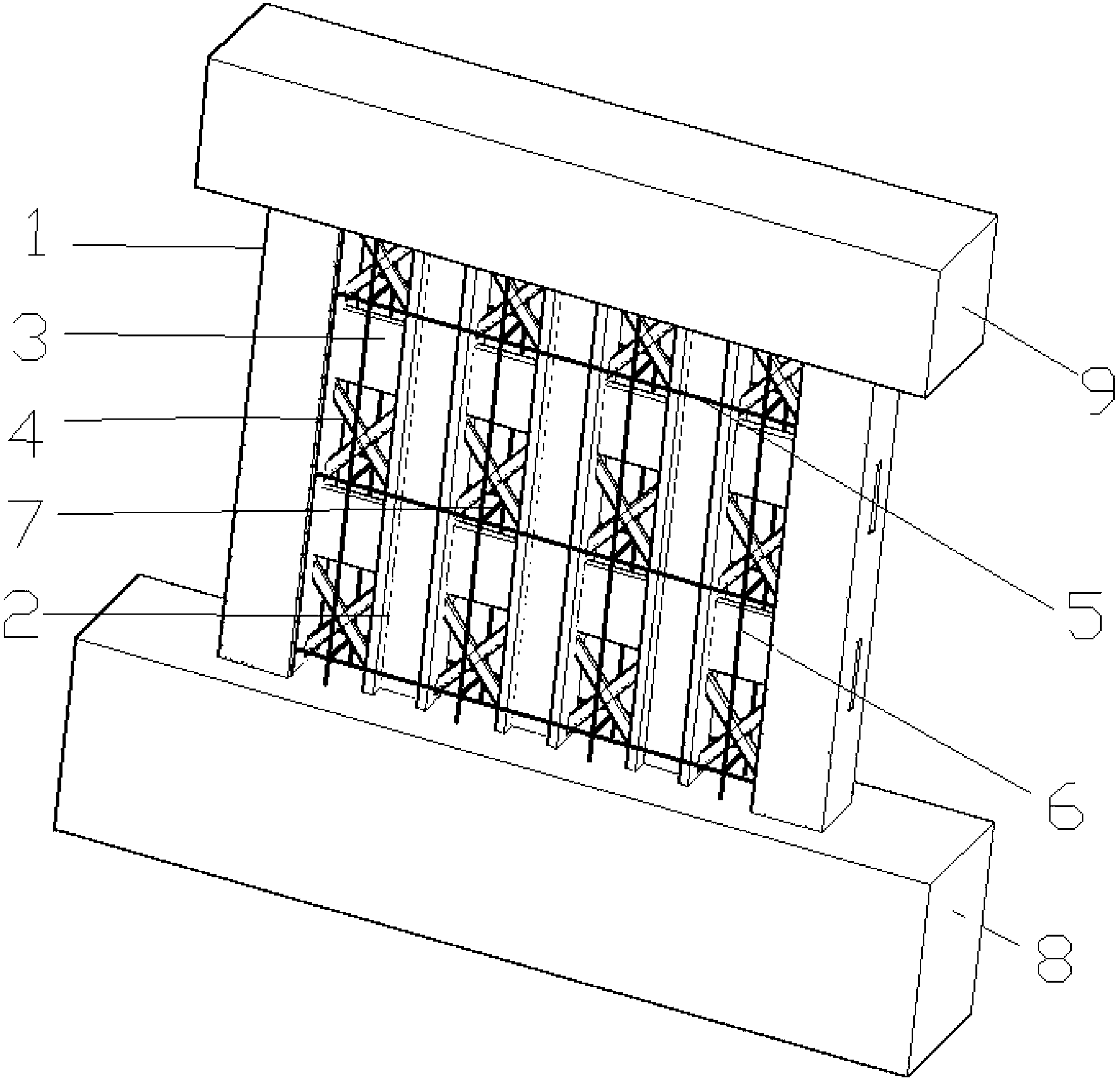
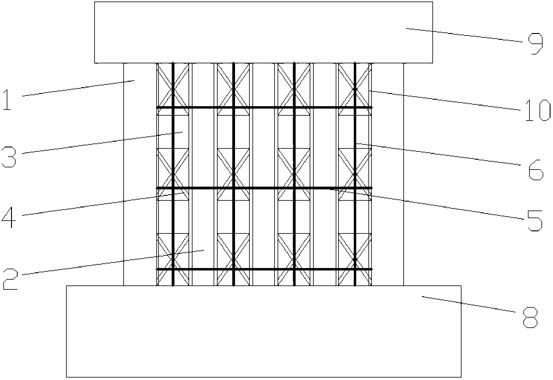
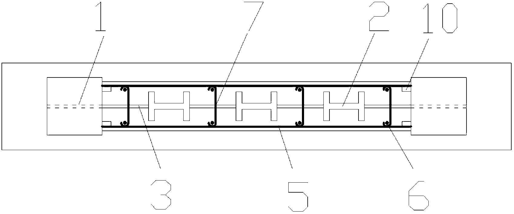
[0037] A structural unit of the "steel column-steel beam-steel brace" shear wall embedded between steel tube concrete columns is as follows: Figure 1-Figure 6 shown.

[0038] The "steel column-steel beam-steel brace" shear wall is embedded between the steel tube concrete columns, and the fabrication sequence is as follows:

[0039] 1) Fabricate the CFST frame column 1 and the steel core column 2, weld and connect horizontally distributed steel bars 5 on the side steel plate of the CFST frame column 1 and vertically connect the steel plates 10, and the steel vertically connecting steel plates and the CFST frame column 1 adopt steel of equal strength;

[0040] 2) Bind the vertically distributed steel bars 6 of the shear wall, the steel bars of the lower frame beam or the foundation beam 8, and insert the steel pipe concrete frame column 1, the steel core column 2, and the v...


PUM


Abstract

The invention provides a shear wall with 'profile steel column-steel beam-steel support' embedded between steel tube concrete columns and a manufacturing method, belonging to the field of steel-concrete combined shear walls. The shear wall is composed of steel tube concrete side frame columns, profile steel core columns, steel plate beams, steel plate supports and a reinforced concrete shear wall body. Steel tube concrete side frame columns are arranged at two ends of the shear wall; a plurality of profile steel core columns in parallel are arranged between the steel tube concrete side frame columns; the steel tube concrete side frame columns and the profile steel core columns and the profile steel core columns are connected by using the steel plate beams and the steel plate supports; the shear wall reinforcing steel bars are strapped; and the concrete is cast so as to form the shear wall with 'profile steel column-steel beam-steel support' embedded between the steel tube concrete columns. Compared with ordinary steel tube concrete side frame shear walls and steel plate shear walls, the shear wall has the advantages that the bearing ability is improved, bearing force and rigidness attenuation slow down and later quake resistance is stable; with the ''profile steel column-steel beam-steel support'' steel structure skeleton, the ductility and the energy consumption property of the shear wall are improved and the quake resistance is superior; the steel structure is convenient to construct; and the shear wall can be used in high-stored or large complex multilayered buildings.

Description

technical field [0001] The present invention is a kind of "steel column-steel beam-steel support" shear wall embedded between steel pipe concrete columns and its method, which belongs to a new type of steel-concrete composite shear wall which consumes the energy of the earthquake input structure and improves the seismic performance of the structure. and its production method. Background technique [0002] Shear wall is the most widely used lateral force component in high-rise buildings, and the seismic performance of shear wall is very important to the overall seismic safety of the structure. The existing reinforced concrete shear walls have poor ductility under earthquake action and are prone to brittle failure, which is very detrimental to the seismic performance of the overall structure. The hybrid structure composed of steel structure and concrete structure has become one of the main structural forms of high-rise and super high-rise buildings because of the advantages o...

Claims


Application Information

Patent Timeline
Patent Type & Authority Applications(China)
IPC IPC(8): E04B2/58E04B2/64E04G21/00
Inventor 曹万林于传鹏董宏英张建伟
Owner BEIJING UNIV OF TECH
Why Eureka
Try Eureka