High efficiency ventilation device for crankcase

A crankcase ventilation, high-efficiency technology, applied in crankcase ventilation, engine components, machines/engines, etc., can solve the problems of pollution, high oil consumption, no filter device, etc., to reduce pollutant emissions and reduce oil consumption. efficiency, complete effect of oil and gas separation

Active Publication Date: 2012-10-03
WUXI KIPOR POWER CO LTD
View PDF8 Cites 5 Cited by
  • Summary
  • Abstract
  • Description
  • Claims
  • Application Information

AI Technical Summary

Problems solved by technology

[0002] In order to solve the problems of blue smoke from diesel engine burning oil and high oil consumption rate, most diesel engines are equipped with an oil-gas separator device at present.
One of the traditional solutions is to set a labyrinth oil-gas separation structure on the diesel engine cylinder head cover or the diesel engine body. This solution has the following technical defects. When casting a diesel engine body, it is not easy to cast a complex oil-gas separation structure, especially Body made of cast iron
[0003] At present, there are two kinds of relatively advanced oil-gas separator devices. One is the crankcase ventilation device mentioned in the CN101984225 cover integrated crankcase ventilation device patent technology. Condensation chamber, the advantage of this device is that compared with the traditional crankcase ventilation device, the oil and gas separation effect is better, but the disadvantage is that there is no filter device, and the effect of complete separation of oil and gas cannot be achieved, and the separated gas also contains fine oil droplets , directly discharged into the atmosphere, will still cause pollution to the atmosphere; the other is the crankcase ventilation device mentioned in the CN101328824 crankcase ventilation device patent technology of a V-type diesel engine. An oil baffle is set up, and the oil-gas separation chamber and the pressure control chamber are formed by the isolation of the oil baffle. The check valve parts are installed in the control chamber. The advantages of this device are: it can ensure that the pressure in the crankcase is reasonable and stable, and When removing excess gas in the crankcase, the oil mist can pass through a long path and improve the effect of oil mist removal. However, the disadvantage of this device is that because there is no real oil and gas filter device, it can only improve the effect of oil mist removal, but cannot eradicate the oil mist in the crankcase. After the exhausted oil mist passes into the air intake system, there will still be a slight phenomenon of burning oil

Method used


Image

  • High efficiency ventilation device for crankcase
  • High efficiency ventilation device for crankcase
  • High efficiency ventilation device for crankcase

Examples


Embodiment Construction

[0017] Below the present invention will be further described in conjunction with the embodiment in the accompanying drawing:

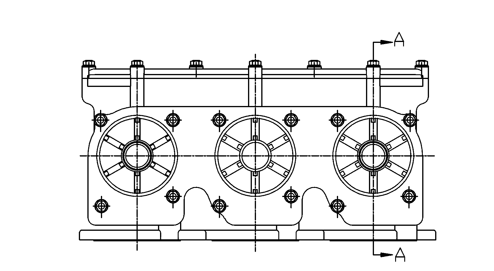
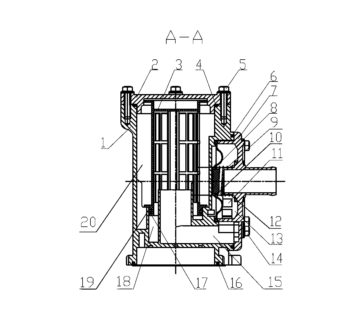
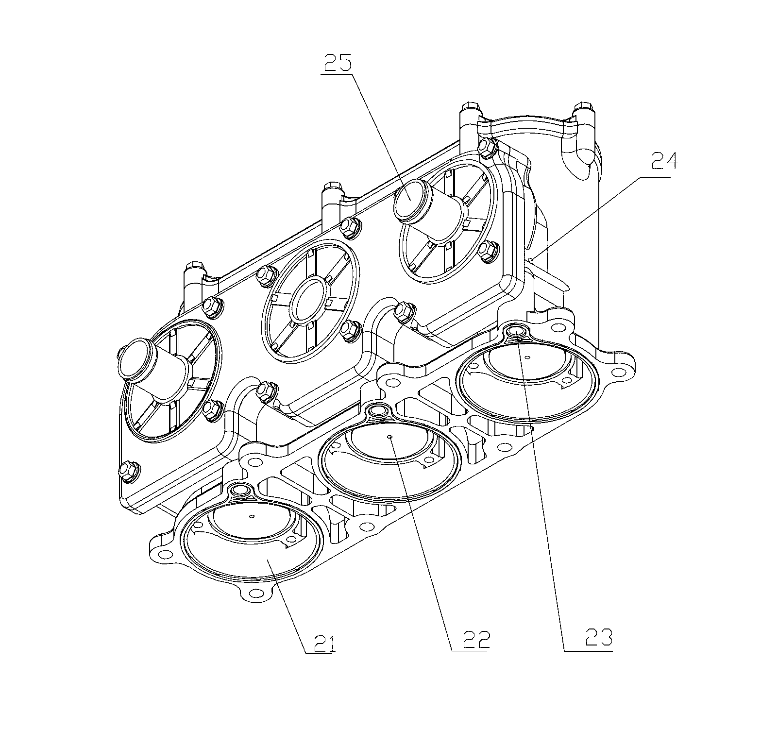
[0018] Such as Figure 1 to Figure 6 As shown, it includes oil-gas separator body 1, oil-gas separator upper cover 2, oil-gas separator core part 3, oil-gas separator upper cover sealing ring 4, oil-gas separator upper cover fastening bolt 5, oil-gas separator side cover sealing ring 6. Oil and gas separator side cover 7, oil and gas separator diaphragm 8, oil and gas separator diaphragm spring 9, oil and gas separator diaphragm boss 10, ventilation window 11, diaphragm spring positioning shaft 12, first chamber 13, oil and gas Separator side cover fastening bolt 14, second chamber 15, oil-gas separator body seal ring 16, oil-gas separator core part seal ring 17, oil return chamber 18, O-shaped groove 19, third chamber 20, air inlet 21 , the first oil return hole 22, the second oil return 23, the vent hole 24, the air outlet 25, the first oil-gas sepa...


PUM


Abstract

The invention mainly relates to a high efficiency ventilation device for a crankcase. The high efficiency ventilation device comprises an oil-gas separator body, an upper cover of the oil-gas separator, core parts of the oil-gas separator, an upper cover sealing ring of the oil-gas separator, side cover sealing rings of the oil-gas separator, side covers of the oil-gas separator, diaphragms of the oil-gas separator, diaphragm springs of the oil-gas separator, a sealing ring of the oil-gas separator and core part sealing rings of the oil-gas separator; the whole high efficiency ventilation device for the crankcase is arranged on a gear chamber of a diesel engine through bolts; the three core parts of the oil-gas separator which can be interchanged are arranged on the oil-gas separator body; the core part sealing rings of the oil-gas separator are arranged between the oil-gas separator body and the core parts of the oil-gas separator and used for sealing; and the two diaphragms and the two diaphragm springs are arranged in the cavity formed by the oil-gas separator body and the side covers of the oil-gas separator. The high efficiency ventilation device has the advantages of compete seperation of oil and gas, high filtration efficiency and accuracy, capability of effectively reducing emission and oil consumption rate, easiness in installation, convenience in maintenance, good reliability and the like.

Description

technical field [0001] The invention relates to a ventilation device for a crankcase of a diesel engine, belonging to the technical field of power devices. Background technique [0002] In order to solve the problems of blue smoke from diesel engine burning oil and high oil consumption rate, most diesel engines are currently equipped with an oil-gas separator device. One of the traditional solutions is to set a labyrinth oil-gas separation structure on the diesel engine cylinder head cover or the diesel engine body. This solution has the following technical defects. When casting a diesel engine body, it is not easy to cast a complex oil-gas separation structure, especially Body made of cast iron. [0003] At present, there are two kinds of relatively advanced oil-gas separator devices. One is the crankcase ventilation device mentioned in the CN101984225 cover integrated crankcase ventilation device patent technology. Condensation chamber, the advantage of this device is th...

Claims


Application Information

Patent Timeline
Patent Type & Authority Applications(China)
IPC IPC(8): F01M13/04F01M13/02
Inventor 肖亨琳高文海
Owner WUXI KIPOR POWER CO LTD
Why Eureka
Try Eureka