
Engine used for generator

A technology for engines and generators, which is applied in the cooling of machines/engines, engine components, and engines. It can solve the problems of difficult control, complex installation structure, and many cooling pipe parts, and achieve convenient and reliable installation, lower operating temperature, and better performance. The effect of the cooling effect

Inactive Publication Date: 2012-10-03
CHONGQING RATO POWER
View PDF7 Cites 7 Cited by
  • Summary
  • Abstract
  • Description
  • Claims
  • Application Information

AI Technical Summary

Problems solved by technology

In this engine-type generator, the cooling of the engine actually adopts the form that the engine cooling air passage and the generator cooling air passage are parallel, that is to say, the two cooling passages are independent, so the result: one is In this scheme, the cooling air that cools the generator has not been well utilized; second, there are many components that constitute the cooling pipeline, which is not conducive to the control of product cost
In addition, the installation structure of each component is complicated and difficult to control

Method used


Image

  • Engine used for generator
  • Engine used for generator
  • Engine used for generator

Examples


Embodiment Construction

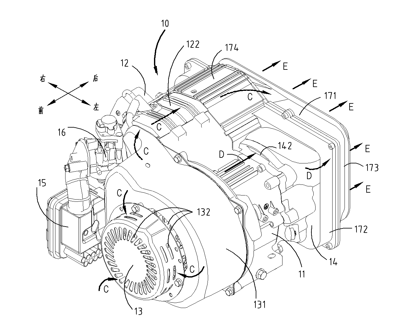
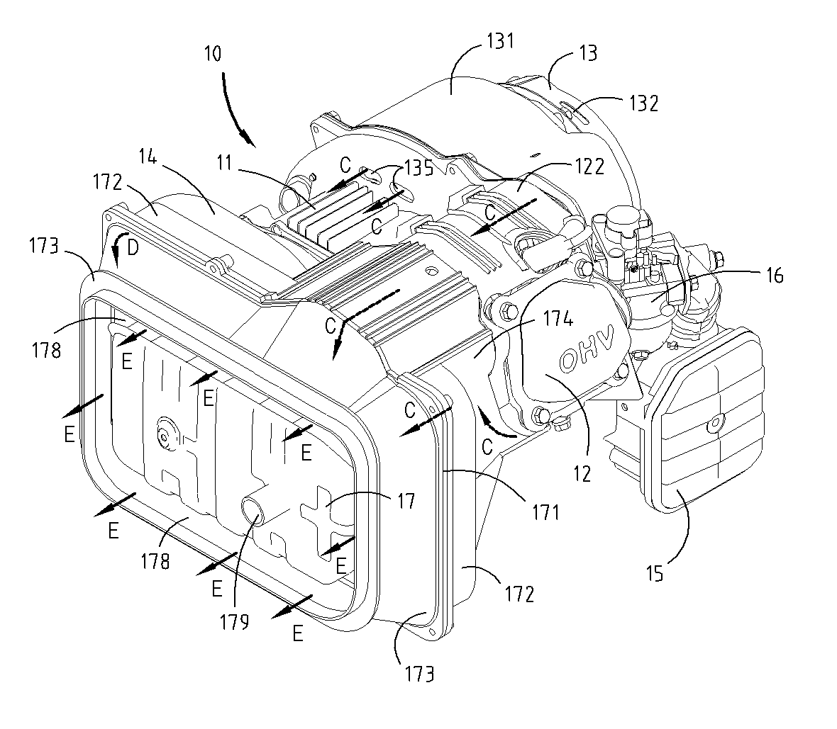
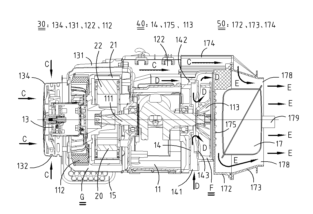
[0030] Next, an engine for a generator according to an embodiment of the present invention will be described with reference to the drawings. The orientation referred to in the description, with figure 1 The orientation indicated in is the reference.

[0031] figure 1 , figure 2 It is a perspective view of different viewing directions of the generator engine of the embodiment of the present invention, image 3 yes figure 1 A sectional view of the engine for a medium generator along the vertical direction of the crankshaft. The generator engine includes an engine 10 and a generator 20 driven by the engine 10 . Engine 10 mainly includes crankcase 11, cylinder block 12, hand starter 13, air filter 15, carburetor 16, muffler 17 and fuel oil tank (because the fuel oil tank for generator is usually arranged on the frame, so it is not shown in the figure show). There is a crankshaft 111 in the crankcase 11, and when the engine 10 is working, the crankshaft 111 freely rotates o...


PUM


Abstract

The invention provides an engine used for a generator, which has the advantages of simple air flue structure and component saving, can reasonably utilize cooling air, effectively improves the cooling effect of the engine, and can be simply installed in an easy control mode. The engine used for the generator comprises a generator, an engine used for driving the generator, a first cooling structure, a second cooling structure and a silencer cover, wherein the first cooling structure is used for forming a first cooling air flue for cooling the cylinder blocks of the generator and the engine; the second cooling structure is used for forming a second cooling air flue for cooling the crankcase of the engine; the silencer cover consists of an inner cover and an outer cover; a gap is formed between the silencer cover and a silencer; a third cooling air flue for cooling the silencer is formed; and the third cooling air flue is respectively communicated with the first cooling air flue and the second cooling air flue.

Description

technical field [0001] The invention relates to an engine for a generator, in particular to a cooling air duct. Background technique [0002] The Chinese patent publication number CN1800600A discloses an engine generator. The engine-type generator has an engine cooling air duct through which the cooling air for cooling the engine and the muffler passes, and an engine cooling air duct through which the cooling air duct for cooling the generator passes, and an integrally formed exhaust duct constitutes a The cooling air of the engine cooling air passage is discharged to the engine duct outside the engine generator and the cooling air passing through the generator cooling air passage is discharged to the generator duct outside the engine generator. In this engine-type generator, the cooling of the engine actually adopts the form that the engine cooling air passage and the generator cooling air passage are parallel, that is to say, the two cooling passages are independent, ...

Claims


Application Information

Patent Timeline
Patent Type & Authority Applications(China)
IPC IPC(8): F01P5/02F01P5/06F01P1/02F01P1/06H02K9/04
Inventor 杨希波杨佺
Owner CHONGQING RATO POWER
Learn More