Supercharge Your Innovation With Domain-Expert AI Agents!

Drainage pump for air conditioner

A technology for drainage pumps and air conditioners, which is applied in the direction of pumps, pump components, and parts of pumping devices for elastic fluids, etc., which can solve the problems of redundant installation space for air conditioners, achieve simple structure, reduce occupied space, and improve sensitivity Effect

Active Publication Date: 2012-10-03
SAGINOMIYA SEISAKUSHO INC
View PDF8 Cites 9 Cited by
  • Summary
  • Abstract
  • Description
  • Claims
  • Application Information

AI Technical Summary

Problems solved by technology

[0008] In this way, since the float switch or the drain water level sensor is arranged outside the drain pump in the prior art, redundant installation space is required in the air conditioner

Method used


Image

  • Drainage pump for air conditioner
  • Drainage pump for air conditioner
  • Drainage pump for air conditioner

Examples


Embodiment Construction

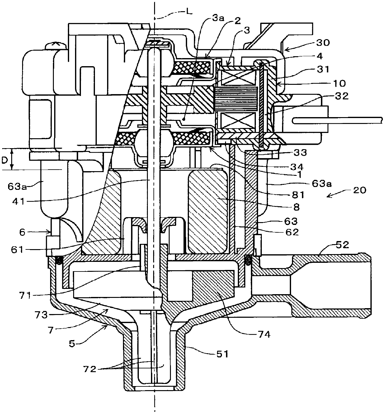
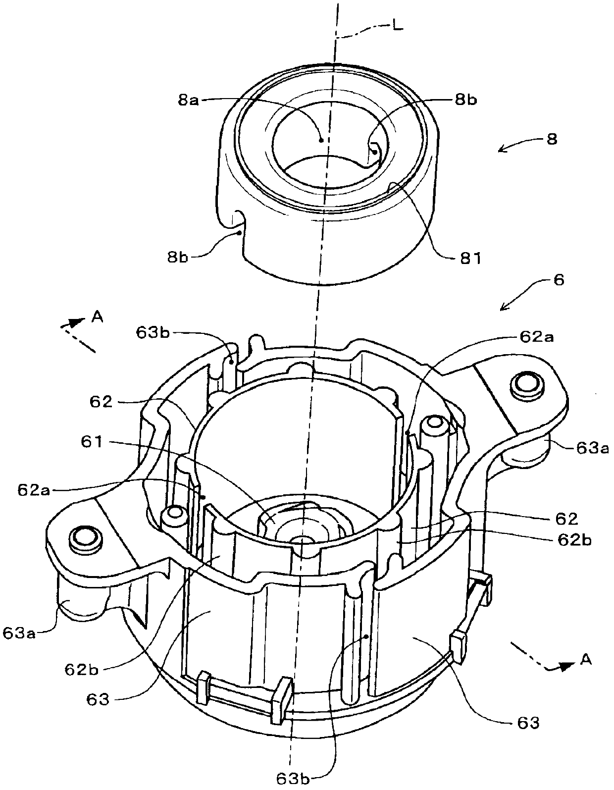
[0024] Next, a drain pump for an air conditioner according to the present invention will be described with reference to the drawings. figure 1 It is a partially cutaway side view of the drain pump for an air conditioner according to the embodiment, figure 2 It is a perspective view of the floating body and the cover case of the drain pump for the same air conditioner. also, figure 1 and figure 2 The A-A profile corresponds. In the following description, the drain pump for an air conditioner is simply referred to as a "drain pump". This drain pump includes a motor unit 10 , a pump unit 20 and a fixing unit (bracket) 30 .

[0025] The motor unit 10 includes bearing assemblies 1 and 2 , a stator circuit unit 3 and a rotor 4 . A through hole 3a is formed in the center of the motor part 10, and the bearing assembly 1, 2 is arranged in the opening of the through hole 3a, and the rotor 4 is arranged in the through hole 3a, and the drive shaft 41 of the rotor 4 is driven by the...


PUM


Abstract

The present invention relates to a drainage pump for an air conditioner. In the situation of detecting drainage water level, occupied space inside the air conditioner can be reduced without externally arranging a sensor. In a cover shell body (6) of a pump part (20), a horizontal wall (62) and an external wall (63) are formed as a maze structure to support a motor part (10). A cylindrical floating body (8) which can be embedded with a dehydration part (61) is arranged on the inner side of the horizontal wall (62) and the external wall (63). A magnetic body (81) is glued on the surface of the motor part (10) side of the floating body (8). In a stator circuit part (3) of the motor part (10), a stator unit (32), a circuit board (33) and a magnetic switch (34) are embedded inside a resin molding part (31). The magnetic switch (34) is used for detecting the magnetic field of the magnetic body (81) and floating of the floating body (8).

Description

technical field [0001] The present invention relates to a drain pump for an air conditioner for draining drain water (condensed water) accumulated in a drain pan of the air conditioner. Background technique [0002] Conventionally, in an air conditioner, in order to control driving and stopping of a drain pump that discharges drain water (condensed water) accumulated in the drain pan, it is necessary to detect the amount of water accumulated in the drain pan. Therefore, Japanese Patent Laid-Open No. 2001-12793 (Patent Document 1) and Japanese Patent Laid-Open No. 2004-85001 (Patent Document 2) disclose a water level (discharge water level) for detecting the drain water (condensed water) in the drain pan. ) of the float switch device. In addition, JP 2010-7906 A (Patent Document 3) discloses a device including a drain water level sensor for detecting the drain water level in order to operate the sterilizer. [0003] prior art literature [0004] Patent Document 1: Japanese...

Claims


Application Information

Patent Timeline
Patent Type & Authority Applications(China)
IPC IPC(8): F04D29/42
Inventor 小野寺康明
Owner SAGINOMIYA SEISAKUSHO INC
Features
  • R&D
  • Intellectual Property
  • Life Sciences
  • Materials
  • Tech Scout
  • Unparalleled Data Quality
  • Higher Quality Content
  • 60% Fewer Hallucinations
Learn More