Pipeline supporting device and mounting method thereof

A pipeline support and installation method technology, which is applied in the direction of pipeline support, pipeline protection, pipeline protection through heat insulation, etc., can solve the problems of damaging the waterproof protective layer and waterproof layer, destroying the use function of buildings, and disorderly arrangement of brackets, etc., and achieves improvement. Waterproof ability, reduce cold bridge effect, and ensure the effect of waterproof performance

Active Publication Date: 2012-10-03
CHENGDU SIXTH CONSTR ENG
View PDF7 Cites 6 Cited by
  • Summary
  • Abstract
  • Description
  • Claims
  • Application Information

AI Technical Summary

Problems solved by technology

[0004] However, the support base of the pipe support device in the prior art passes through the expansion screw and is fixedly installed on the top surface of the building. When the expansion screw passes through the support base, it will not only penetrate into the top surface layer of the building , will also penetrate down into the waterproof protective layer, waterproof layer, etc. of the building until the roof structure layer, so that the expansion screws will destroy the waterproof protective layer and waterproof layer, so that the waterproof ability of the top surface of the building will be reduced or even water leakage will occur. destroy the function of the building
In addition, the heat in the pipeline is easily concentrated and transferred quickly from the pipeline where the main body of the bracke

Method used


Image

  • Pipeline supporting device and mounting method thereof
  • Pipeline supporting device and mounting method thereof
  • Pipeline supporting device and mounting method thereof

Examples


Example Embodiment

[0028] The technical solutions in the embodiments of the present invention will be clearly and completely described below in conjunction with the accompanying drawings in the embodiments of the present invention. Obviously, the described embodiments are only a part of the embodiments of the present invention, rather than all the embodiments. Based on the embodiments of the present invention, all other embodiments obtained by those of ordinary skill in the art without creative work shall fall within the protection scope of the present invention.

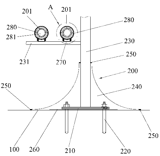
[0029] Please refer to figure 1 , figure 1 It is a schematic diagram of the structure of the pipeline support device of the present invention. As shown in the figure, the pipeline support device 200 includes a support base 210, a chemical bolt 220, a support body 230, a cement mortar block 240, a waterproof sealant 250, and a waterproof coating film 260. The bracket base 210 is fixedly installed on the top surface 100 of the building; ...


PUM


Abstract

The invention discloses a pipeline supporting device and a mounting method thereof. The pipeline supporting device comprises a support frame base, a support frame body, cement mortar blocks and waterproof sealants; the support frame base is installed on the top surface of a building; the two ends of the support frame body are respectively connected with the support frame base and pipelines; the cement mortar blocks surround the support frame body, and the bottom surfaces of the cement mortar blocks are in contact with the top surface of the building; and the waterproof sealants are connected with the cement mortar blocks, the top surface of the building and the support frame body. The pipeline supporting device also comprises chemical bolts, a waterproof coating and heat insulation bodies; through the chemical bolts, the support frame base is fixedly arranged on the top surface of the building; the waterproof coating is respectively connected with the top surface of the building and the support frame base; the heat insulation bodies are installed at the upper end of the support frame body; and the pipelines are borne on the heat insulation bodies. The pipeline supporting device and the mounting method thereof have the beneficial effects that the waterproof ability of the top surface of the building is enhanced, the transition and the smoothness of heat in the pipelines are ensured, the generation of cold bridge effect is reduced and avoided, the service lives of the pipelines are prolonged, and the potential safety hazards caused by the use of the whole building are reduced.

Description

technical field [0001] The invention relates to the field of building pipelines, in particular to a pipeline support device and an installation method thereof. Background technique [0002] In various large-scale residential buildings and public buildings, there are many and many types of pipelines in water supply, drainage, heating and air conditioning systems. Therefore, pipeline installation occupies a relatively large proportion in the entire construction project. Pipelines not only affect the appearance of the entire building, but are also an important part of the entire building with potential safety hazards. [0003] The installation of each pipeline is generally by installing a bracket support device on the top surface of the building, installing the pipeline on the bracket, so that each pipeline is supported by the support device. The existing pipeline support device includes a bracket base, a bracket body, cement mortar blocks and waterproof sealant, and for the s...

Claims


Application Information

Patent Timeline
IPC IPC(8): F16L3/00F16L59/135
Inventor 黄良刘宏车汪速高照林
Owner CHENGDU SIXTH CONSTR ENG
Why Eureka
Try Eureka