Reflector, illumination device with reflector, and method for manufacturing reflector

A reflector and reflective hole technology, applied in the field of reflectors, can solve the problems of not having enough space to use the reflector, difficult to obtain thickness, uniform coating, etc.

Inactive Publication Date: 2012-10-03
OSRAM GMBH
View PDF0 Cites 0 Cited by
  • Summary
  • Abstract
  • Description
  • Claims
  • Application Information

AI Technical Summary

Problems solved by technology

However, in smaller and more slender reflectors, especially at the bottom of the reflector, it is difficult to obtain a coating with uniform thickness by vacuum coating process
In order to obtain a uniform thickness of the coating, in the prior art usually try to enlarge the size of the reflector, but sometimes the size of the product is limited, there is not enough space to use such a large size reflector
Of course, the anodizing process is also a conventional solution, and a coating with uniform thickness can be obtained on reflectors of any shape and size. However, the optical efficiency of the coating obtained by this process is much lower than that of the vacuum coating process.

Method used


Image

  • Reflector, illumination device with reflector, and method for manufacturing reflector
  • Reflector, illumination device with reflector, and method for manufacturing reflector
  • Reflector, illumination device with reflector, and method for manufacturing reflector

Examples


Embodiment Construction

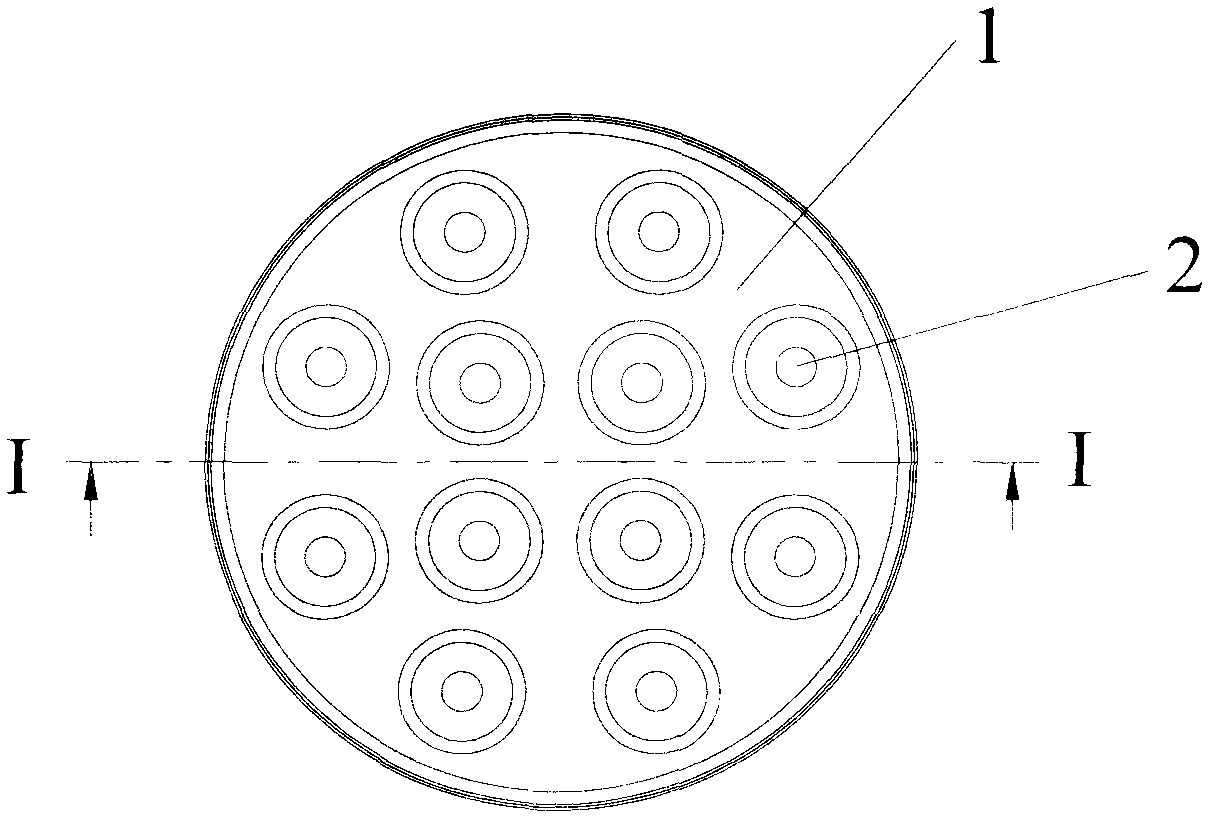
[0024] figure 1 A top view of the reflector according to the present invention is shown, and it can be seen from the figure that the reflector includes a base body 1 and a plurality of reflection holes 2 arranged in the base body 1 . The reflection holes 2 are arranged in the base body 1 in a matrix.

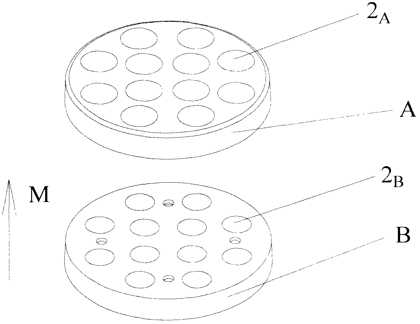
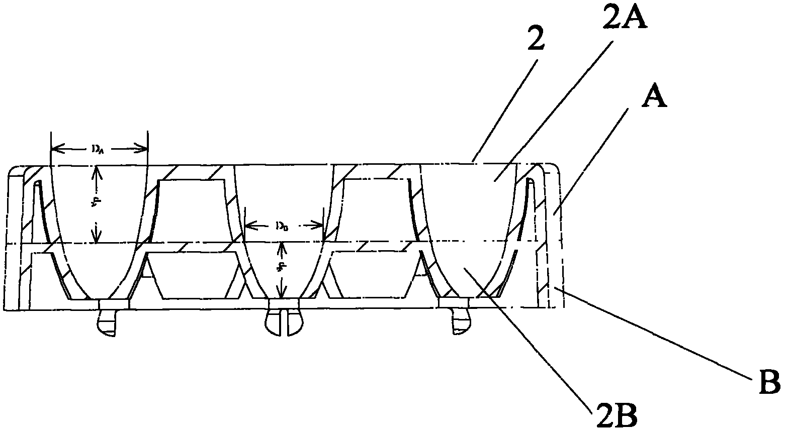
[0025] figure 2 Shown is an exploded schematic view of the reflector according to the present invention. It can be seen from the figure that the sub-base A and the sub-base B are stacked together in a direction parallel to the optical axis M, thereby forming a base 1, wherein the sub-base A sub-base reflection hole 2 A and sub-reflective hole 2 of sub-base B B Aligned with each other, reflective holes 2 are formed, thereby constituting a reflector. Of course, the sub-bases of the reflector according to the present invention can also be stacked on each other in a direction perpendicular to the optical axis M (not shown), wherein the split planes pass through each reflection ...


PUM


Abstract

The invention relates to a reflector for illumination equipment. The reflector comprises a substrate (1) and at least one reflecting hole (2) formed in the substrate (1), wherein the substrate (1) comprises a plurality of sub substrates (A and B); at least one sub reflecting hole (2A or 2B) is formed in each sub substrate (A or B); and the sub substrates (A and B) can be stacked together, so that the sub reflecting holes (2A and 2B) of the sub substrates (A and B) are aligned to form the reflecting hole (2). According to the reflector, a plating with uniform thickness can be obtained during vacuum plating, so that high reflectivity and optical efficiency are achieved. The invention also provides the illumination equipment with the reflector, and a method for manufacturing the reflector.

Description

technical field [0001] The invention relates to a reflector, an illuminating device with the reflector and a manufacturing method of the reflector. Background technique [0002] Reflectors are very common components in lighting equipment. In order to obtain high optical efficiency, coatings are required on the reflector. Two processes of vacuum coating and anodic oxidation are generally used in the prior art. However, in smaller and more slender reflectors, especially at the bottom of the reflector, it is difficult to obtain a coating with a uniform thickness through a vacuum coating process. In order to obtain a coating with a uniform thickness, it is generally attempted to enlarge the size of the reflector in the prior art, but sometimes the size of the product is limited, and there is not enough space to use such a large-sized reflector. Of course, the anodizing process is also a conventional solution, and a coating with uniform thickness can be obtained on reflectors ...

Claims


Application Information

Patent Timeline
IPC IPC(8): F21V7/22
CPCF21V7/10F21Y2101/02F21Y2115/10
Inventor 武辉戴成龙古念松袁海平
Owner OSRAM GMBH
Why Eureka
Try Eureka