

Process for production of silicon tetrachloride
A manufacturing method and technology of silicon tetrachloride, applied in chemical instruments and methods, halogenated silicon compounds, inorganic chemistry, etc., can solve problems such as difficult catalytic ability
- Summary
- Abstract
- Description
- Claims
- Application Information
AI Technical Summary
Problems solved by technology
Method used
Image

Examples
Embodiment 1)
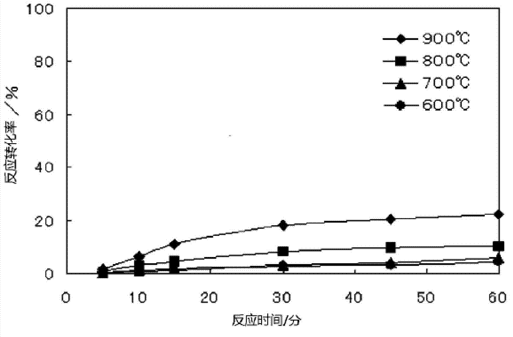
[0068] As the silicic acid-containing substance, 100 mg of silica was used, and as the carbon-containing substance, 45 mg of ash produced by an industrial process was used. The ashes produced by industrial processes used in this example are those produced by waste incineration facilities, and were used without pulverization. Silica is used after being pulverized by a ball mill. It should be noted that the surface area (BET method) of the pulverized silica is 2160cm 2 / g, the silica content is 95.2% by mass, the carbon content of the ash produced by the industrial process used is 85.2% by mass, the average particle size is 17μm, and the surface area (BET method) is 19m 2 / g.
[0069] After the carbonaceous material is added to the silicic acid-containing material and mixed, a reaction mixture is obtained. It should be noted that the amount of the carbon-containing substance added is such that the number of moles of C contained in the reaction mixture becomes twice the number...
Embodiment 2)
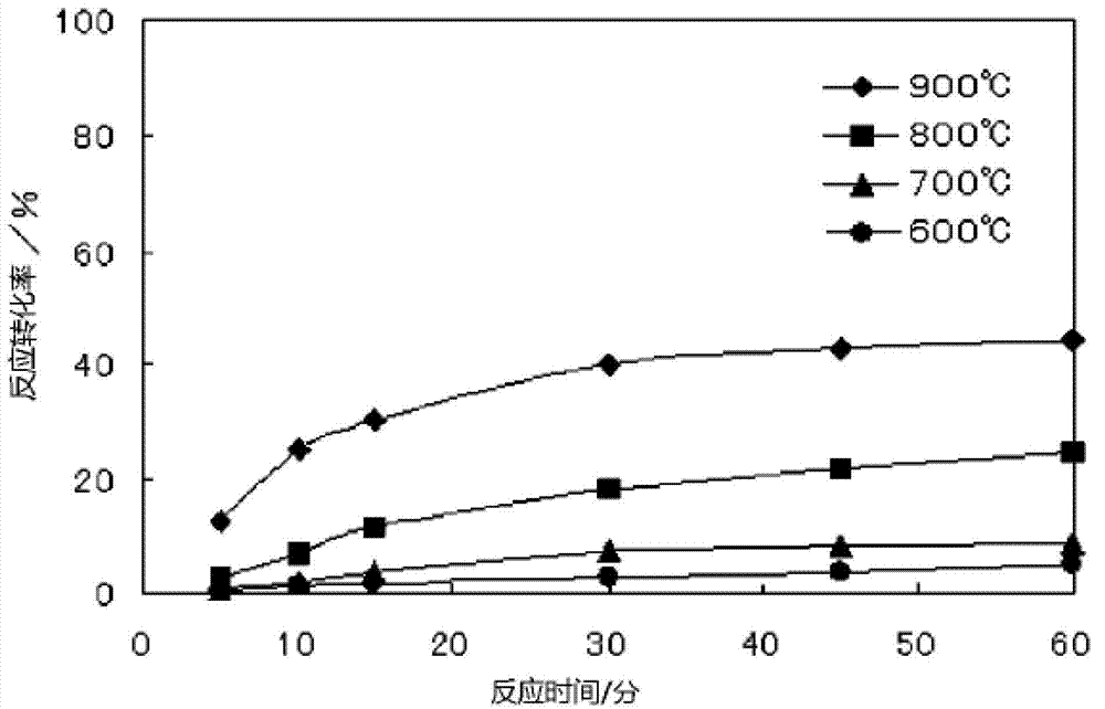
[0076] 100 mg of silica was used as the silicic acid-containing substance, and 49 mg of ash generated from a power generation facility was used as the carbon-containing substance. The ash generated by the power generation facility used in this example is ash generated by IGCC, and it was used without pulverization. It should be noted that the surface area (BET method) of the pulverized silica is 2160cm 2 / g, the silica content is 95.2% by mass, the carbon content of the IGCC ash used is 79.0% by mass, the sulfur content is 5.9% by mass, the average particle size is 8μm, and the surface area (BET method) is 23m 2 / g. The reaction mixture was produced by the same technique as in Example 1, and was brought into contact with pure chlorine gas at 600 to 900° C. to carry out chlorination reaction. The time change of the reaction conversion rate to silicon tetrachloride at each reaction temperature is shown in figure 2 .
Embodiment 3)
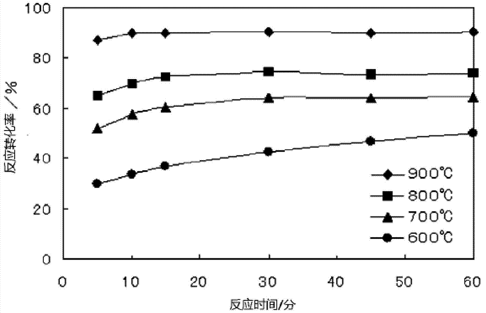
[0078] As the silicic acid-containing substance, 100 mg of ash of silicic acid biomass was used, and as the carbon-containing substance, 37 mg of ash generated from a power generation facility was used. The ashes of the silicic acid biomass used in the present example are the ash of the biomass saccharification residue generated in the production of bioalcohol, and the ash generated from the power generation facility is the ash generated from the IGCC, and both were used without pulverization. It should be noted that the silica content of the ash of silicic acid biomass is 71.8% by mass, the carbon content of the IGCC ash used is 79.0% by mass, the sulfur content is 5.9% by mass, the average particle size is 8 μm, and the surface area ( BET method) is 23m 2 / g. The reaction mixture was produced by the same technique as in Example 1, and was brought into contact with pure chlorine gas at 600 to 900° C. to carry out chlorination reaction. The time change of the reaction conver...
PUM
| Property | Measurement | Unit |
|---|---|---|
| particle diameter | aaaaa | aaaaa |
| particle size | aaaaa | aaaaa |
| particle size | aaaaa | aaaaa |
Abstract
Description
Claims
Application Information