Manufacturing method of Mo alloy sputtering target materials and sputtering target materials

A technology for sputtering targets and manufacturing methods, which is applied in the manufacture of Mo alloy sputtering targets and the field of Mo alloy sputtering targets, can solve the problems of low adhesion of substrates, and achieve excellent adhesion, low resistance, The effect of improving reliability

Active Publication Date: 2013-06-26
HITACHI METALS LTD
View PDF5 Cites 12 Cited by
  • Summary
  • Abstract
  • Description
  • Claims
  • Application Information

AI Technical Summary

Problems solved by technology

Although Cu can achieve contact with ITO, it has low adhesion to the substrate, so in order to ensure adhesion, it is necessary to form a laminated wiring film in which Cu is covered with pure Mo or Mo alloy.

Method used


Image

  • Manufacturing method of Mo alloy sputtering target materials and sputtering target materials
  • Manufacturing method of Mo alloy sputtering target materials and sputtering target materials

Examples


Embodiment 1

[0056] The following examples are given to illustrate the present invention in detail.

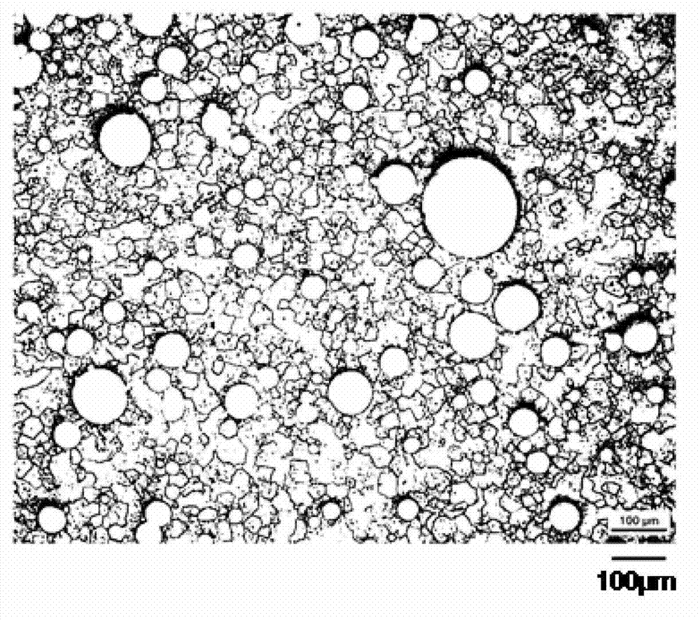
[0057] In order to produce a Mo alloy sputtering target with atomic ratio of 15%Ni-5%Nb-the balance being Mo and unavoidable impurities, Mo powder with a purity of 99.99% and an average particle size of 6μm and the atomization method were prepared. Ni with a purity of 99.9% and an average particle size of 70 μm 3 Nb alloy powder. For comparison, a melting method was attempted, but Mo was still melted and normal alloy lumps could not be produced.

[0058] Each powder was weighed so as to have the above composition, and mixed using a cross rotary mixer to obtain a mixed powder. After that, fill it into a mild steel container with an inner diameter of 133 mm, a height of 30 mm, and a thickness of 3 mm, heat at 450°C for 10 hours for degassing, then seal the mild steel container, and use a hot isostatic pressing (HIP) device at 1180°C, The sintering was carried out by keeping at 148MPa for ...

Embodiment 2

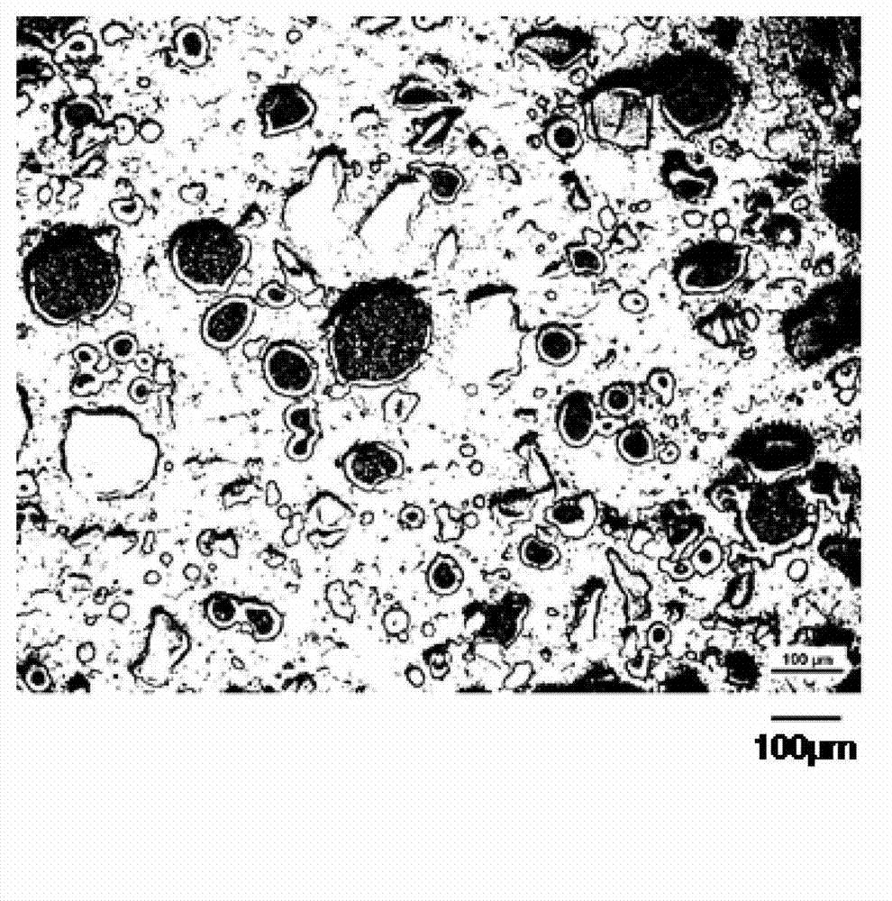
[0068] In order to make a Mo alloy sputtering target with atomic ratio of 20%Ni-10%Nb-the balance is Mo and unavoidable impurities, the following powders are prepared: Mo powder with a purity of 99.99% and an average particle size of 6μm; Ni-30Mo (atomic %) alloy powder with a purity of 99.9% and an average particle size of 100 μm produced by the chemical method; and Nb powder with an average particle size of 85 μm. For comparison, a melting method was attempted, but Mo was still melted and normal alloy lumps could not be produced.

[0069]Each powder was weighed so as to have the above-mentioned composition, and mixed using a cross rotary mixer to obtain a mixed powder. After that, fill it into a mild steel container with an inner diameter of 133 mm, a height of 30 mm, and a thickness of 3 mm, heat at 450°C for 10 hours for degassing treatment, then seal the mild steel container, and use a hot isostatic pressing (HIP) device at 1100°C, Sintering was carried out by keeping it...


PUM

PropertyMeasurementUnit
diameteraaaaaaaaaa
particle sizeaaaaaaaaaa

Abstract

The invention provides a manufacturing method of a Mo alloy sputtering target material and the sputtering target material. The sputtering target material is low in resistance, excellent in heat resistance, moisture resistance, and closeness with a substrate, high in intensity and purity, and non-magnetic, as well as is suitable for electrodes and wiring films. The manufacturing method of the Mo alloy sputtering target material includes mixing Mo powder with more than one or two Ni alloy powder to satisfy the following combination, and then performing pressure sintering. The combination comprises Ni containing 10-49 atom%, Nb containing 1-20 atom%, the total of Ni and Nb less than 50 atom%, and the balance being Mo and unavoidable impurities.

Description

technical field [0001] This invention relates to the manufacturing method of the Mo alloy sputtering target material used for forming the electrode and wiring film for electronic components, and a Mo alloy sputtering target material. Background technique [0002] Flat-panel display devices (flat panel displays) such as liquid crystal displays (Liquid Crystal Display: hereinafter referred to as LCD), plasma display panels (Plasma Display Panel: hereinafter referred to as PDP) that form thin-film devices on glass substrates, and electrophoretic displays used in electronic paper. Low-resistance wiring films are required in thin-film electronic components such as displays and Flat Panel Displays (hereinafter referred to as FPDs) and various semiconductor devices, thin-film sensors, and magnetic heads. For example, FPDs such as LCDs, PDPs, and organic EL displays require a lower resistance of the wiring film due to larger screens, higher definition, and faster response. In addit...

Claims


Application Information

Patent Timeline
Patent Type & Authority Applications(China)
IPC IPC(8): C23C14/34C23C14/14C22C27/04
CPCC22C1/04C22C27/04C23C14/3407C23C14/3414H01J37/3414
Inventor 村田英夫上滩真史井上惠介
Owner HITACHI METALS LTD
Why Eureka
Try Eureka