Microlens production method

一种制造方法、微透镜的技术,应用在透镜、辐射控制装置、照相制版工艺曝光装置等方向,能够解决开口率降低、成品率降低、不能消除相邻透镜间隙等问题,达到聚光效率提高的效果

Active Publication Date: 2012-10-03
NISSAN CHEM CORP
View PDF11 Cites 1 Cited by
  • Summary
  • Abstract
  • Description
  • Claims
  • Application Information

AI Technical Summary

Problems solved by technology

[0006] When using the first method of the prior art, since the pattern layer of the photosensitive lens thermoplastic resin is heat-flowed to form a convex lens shape, welding occurs between adjacent lenses in the heat-flow process, which causes a decrease in yield. reason
In addition, if the distance between the lenses is increased to prevent this phenomenon, the yield will be improved, but there is a problem that a gap is generated between the lenses, which leads to a reduction in the aperture ratio, and the performance of the image sensor is reduced.
[0007] The second method also has a thermal flow process, so it has the same concern
However, the gap between adjacent lenses cannot be eliminated in this method
Furthermore, there is the following problem: the microlens array shape with a high aperture ratio, which is considered ideal in terms of light-gathering efficiency, and has overlap between lenses, cannot be obtained.

Method used


Image

  • Microlens production method
  • Microlens production method
  • Microlens production method

Examples


Embodiment 1

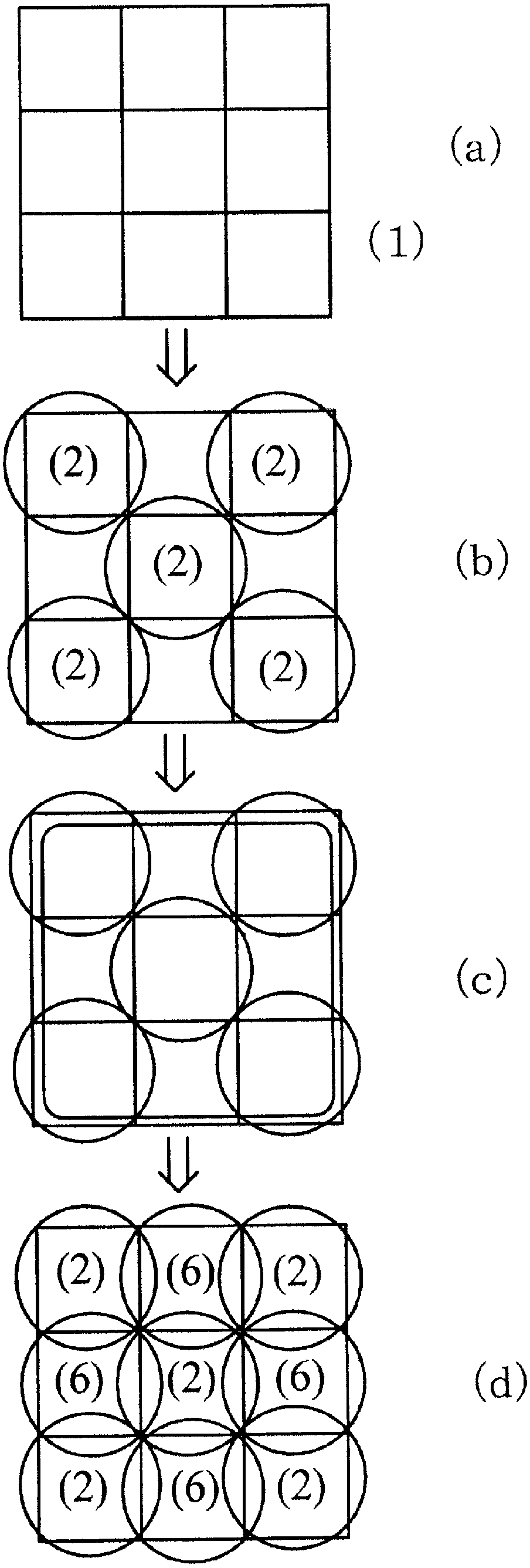
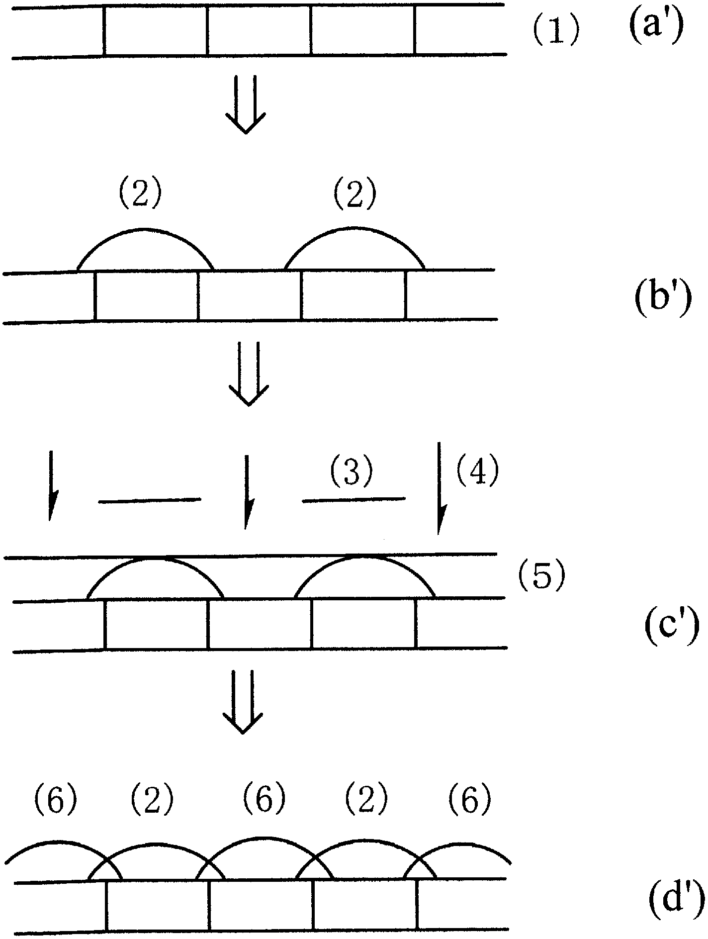
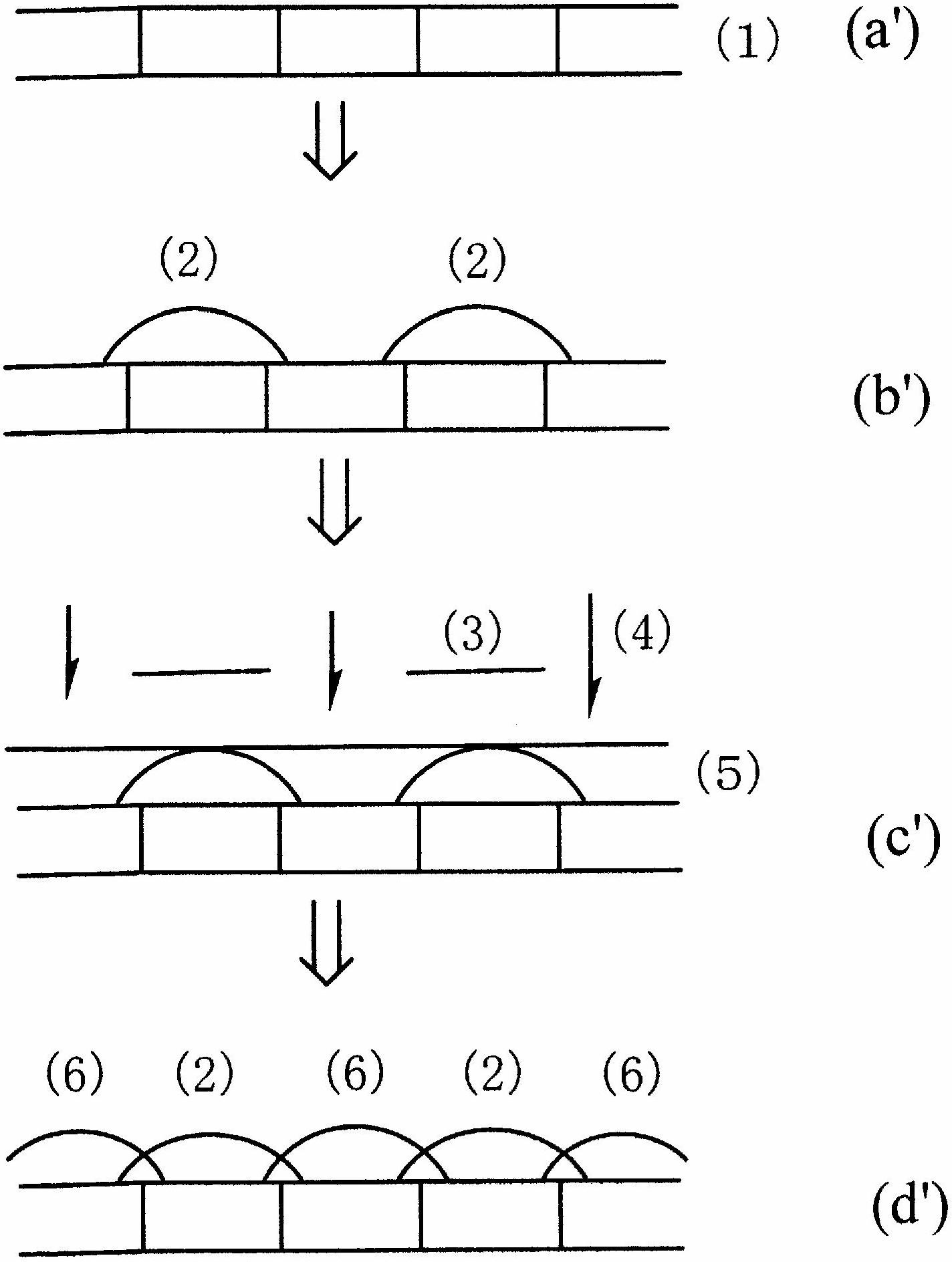
[0065] As the first step, apply a composition for forming a thermosetting microlens on a substrate, expose the formed coating film (the softening point temperature of the coating film is 170°C.) through a grayscale mask, and develop As the pattern of the first microlens ( figure 1 of (b), figure 2 (b')). At this time, the pattern film forms a two-color alternate pattern on the color filter. Next, the lens-shaped pattern film formed by the exposure and development was cured by firing at 140°C, further at 180°C. The diameter of the lens pattern is 2.5 μm. Then, as the second step, the same thermosetting microlens-forming composition as in the first step is used to form the second step through a grayscale mask on the color filter of the portion where the pattern film is not formed in the first step. 2. The lenticular pattern film is then fired at 140° C. for 5 minutes to complete curing accompanied by a crosslinking reaction, and then fired at 180° C. for 5 minutes to form a...

Embodiment 2

[0067] On the same substrate as in Example 1, a thermoplastic microlens-forming composition was used as the first step (the softening point temperature of the coating film formed from the composition is 120°C), and a dot pattern was formed through a binary mask. film (1st microlens) ( figure 1 of (b), figure 2 (b')). At this time, the dot pattern film forms a two-color alternate pattern on the color filter. Next, by performing heat treatment at 160° C., the dot pattern film formed above was heat-flowed to form a lens pattern film. Thereafter, curing is performed by firing at 200°C. The diameter of the lenticular pattern film was 2.5 μm. Then, as the second step, on the color filter of the part where the pattern film is not formed in the first step, a different thermosetting microlens-forming composition (by combining The softening point temperature of the coating film formed by the material is 170°C.) The second lenticular pattern film is formed, followed by firing at 14...


PUM


Abstract

Disclosed is a solid-state image capture element which has high effective sensitivity due to increased microlens formation stability, a reduced the gap between adjacent lenses during microlens formation, excellence in the formation of structures layered between lenses, and excellent control of lens curvature. Also disclosed is a production method for the solid-state image capture element. The disclosed production method for a solid-state image capture element wherein microlenses are arranged on a substrate so as to be adjacent to one another comprises: a first step wherein first microlenses are formed on the surface of a substrate leaving a space wherein second microlenses will be provided; and a second step wherein an overcoat material is applied and then dried on the surface of the substrate whereon the first microlenses have been formed, the resulting substrate is then exposed using a greyscale mask, then second microlenses are formed in the space between adjacent first microlenses, by developing the exposed overcoat material.

Description

technical field [0001] The present invention relates to a solid-state imaging device with a microlens and its manufacturing method. Background technique [0002] As a method of forming microlenses on a substrate, various methods have been studied. [0003] As the first method, the following method (melt method, melt method) is well known: forming a photosensitive thermoplastic resin layer for lenses on the light-receiving part color filter of the image sensor, exposing the resin layer using a photomask having a predetermined pattern, After development, a columnar resist pattern layer is formed at the position corresponding to each light-receiving part, and then heat treatment is performed above the softening point of the thermoplastic resin to cause the resin to flow thermally, thereby causing liquid subsidence at the edge of the pattern layer. Drip, thus forming a convex lens. [0004] As a second method, a method (eching back) is known in which a photosensitive resist fi...

Claims


Application Information

Patent Timeline
Patent Type & Authority Applications(China)
IPC IPC(8): G02B3/00H01L27/14
CPCH01L27/14685H01L27/14627G02B3/0012G02B3/0056G02B1/00G02B3/00G03F7/20H01L27/14H01L27/146
Inventor 荒濑慎哉坂口崇洋
Owner NISSAN CHEM CORP
Why Eureka
Try Eureka