Double-driving parallel sequential supercharging compressor

A sequential supercharging and compressor technology, applied in mechanical equipment, engine function, engine control and other directions, can solve the problems of high manufacturing cost, difficult design and production technology, and difficult promotion, etc., to improve compressor surge, improve Engine performance, effect of widening intake air flow

Active Publication Date: 2012-10-10
康跃科技(山东)有限公司
View PDF3 Cites 23 Cited by
  • Summary
  • Abstract
  • Description
  • Claims
  • Application Information

AI Technical Summary

Problems solved by technology

However, at present, traditional turbochargers basically use a single-impeller single-channel compressor, which is prone to turbocharger surge phenomenon in the low-speed operating range of the engine, and turbocharger flow blockage is prone to occur in the high-speed operating range of the engine, and Cannot effectively meet the higher pressure ratio, flow range and efficiency level that the turbocharger needs to achieve
Therefore, many engine applications are forced to adopt a two-stage turbocharger system. In terms of performance, the two-stage turbocharger system has many advantages, but compared with the traditional single-impeller turbocharger, the two-stage turbocharger The pressure system is bulky and complex in layout, and the design and production technology is difficult and the manufacturing cost is high. This two-stage turbocharging system is only suitable for high-end engines, and it is difficult to promote it.

Method used


Image

  • Double-driving parallel sequential supercharging compressor
  • Double-driving parallel sequential supercharging compressor
  • Double-driving parallel sequential supercharging compressor

Examples


Embodiment 1

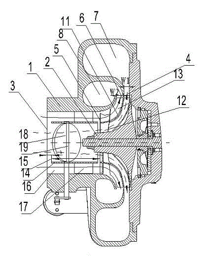
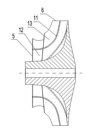
[0057] Example 1, such as figure 1 , figure 2 As shown, a double-drive parallel sequential booster compressor includes a compressor casing 1, a compressor impeller 2 is installed in the compressor casing 1, a compressor flow channel is arranged in the compressor casing 1, and a A compressor air inlet 3 and a compressor air outlet respectively communicated with the compressor flow channel are arranged, and it is characterized in that: the compressor impeller 2 is provided with an impeller inlet flow channel, and the impeller inlet flow channel is connected with the compressor air inlet respectively. 3 communicate with the flow path of the compressor.

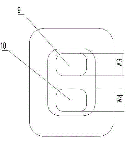
[0058] The compressor runner includes a compressor inner runner 7 and a compressor outer runner 8 arranged side by side on the compressor shell 1; The ratio of the mouth width W2 is 0.1-10.

[0059] A compressor diffuser 4 is provided at the air inlet of the compressor inner flow channel 7 .

[0060] The compressor outlet in...

Embodiment 2

[0074] Example 2, such as Figure 6 , Figure 7 As shown, on the basis of Embodiment 1, the butterfly valve 18 arranged in the inner channel 15 of the air inlet of the compressor is removed, and the position of the inner channel 7 of the compressor near the air outlet 9 of the inner channel of the compressor is set There is an adjustable valve 20, one end of the adjustable valve 20 is connected with a valve shaft 19, and the valve shaft 19 is connected with a control mechanism, and driven by the control mechanism, the opening or closing of the flow channel 7 in the compressor is realized.

[0075] The working process of this embodiment: as Figure 7As shown, when the engine is in the low-speed operating range, the adjustable valve 20 is in a closed state driven by the control mechanism (as shown by the solid line of the adjustable valve in the figure), at this time the centrifugal force generated by the rotation of the fresh air in the compressor impeller 2 Driven by the dri...

Embodiment 3

[0076] Example 3, such as Figure 8 , Figure 9 As shown, on the basis of Example 2, the adjustable valve 20 arranged near the air outlet 9 of the inner runner of the compressor is removed, and the air outlet 6 of the impeller in the diffuser 4 of the compressor is evenly arranged in a circular shape. There are several adjustable guide vanes 21, and the ratio of the number of the fixed guide vanes 17 to the number of the adjustable guide vanes 21 is 0.2-6.

[0077] Such as Figure 10 As shown, each of the adjustable guide vanes 21 is rotatably connected to a shift fork 22, and the fork 22 is rotatably connected to a shift fork plate 23, and the shift fork plate 23 is driven by the control mechanism to rotate to realize the adjustable flow guide The rotation of the vane 21 realizes the opening or closing of the flow channel 7 in the compressor.

[0078] The control mechanism in Embodiment 3 is not limited to the shift fork control mechanism, and any structure of the control ...


PUM


Abstract

The invention discloses a double-driving parallel sequential supercharging compressor which comprises a compressor casing and a compressor impeller installed in the compressor casing. A compressor flow path is arranged in the compressor casing, and a compressor air inlet and a compressor air outlet which both communicate with the compressor flow path are arranged on the compressor casing. The compressor impeller is provided with an impeller air inlet flow path which communicates with the compressor air inlet and the compressor flow path. The double-driving parallel sequential supercharging compressor of the invention can effectively improve the compressor surge when the compressor is under a low speed condition, and effectively expand intake air flow when the compressor is under a middle or high speed condition and improve engine performance. The compressor casing and the compressor impeller of the double-driving parallel sequential supercharging compressor of the invention has good structural inheritance, and engineering is easy to be realized rapidly.

Description

technical field [0001] The invention relates to a booster compressor, in particular to a dual-drive parallel sequential booster compressor with a double-channel compressor casing and a single compressor impeller, which belongs to the field of internal combustion engine booster. Background technique [0002] The turbocharger uses the energy of the exhaust gas discharged from the engine to drive the turbine to rotate, thereby driving the impeller of the compressor coaxial with the turbine to rotate at a high speed. The compressor pushes the compressed air into the engine cylinder, increasing the air volume of the engine. Driven by the flow rate, the combustion is more complete, thereby increasing the power of the engine, reducing fuel consumption, and reducing harmful emissions and noise. [0003] In recent years, with the substantial increase in engine power per liter, the technical indicators of turbocharging also need to be continuously improved, which requires a turbocharg...

Claims


Application Information

Patent Timeline
Patent Type & Authority Applications(China)
IPC IPC(8): F04D29/28F04D29/42F04D29/46F04D27/00
CPCF04D29/28F04D29/46F04D29/42F04D27/00F04D27/0269F04D29/4206F01D9/026F04D29/4213F05D2220/40F05D2240/40F05D2260/60F05D2270/101F04D29/286F05D2250/52F05D2250/51F04D17/10F04D27/0253F04D27/0246F04D29/30F04D29/462
Inventor 王航李永泰朱智富李延召袁道军王艳霞宋丽华
Owner 康跃科技(山东)有限公司
Why Eureka
Try Eureka